Front-end circuit for simultaneous transmission and reception operation

a front-end circuit and simultaneous transmission technology, applied in the field of front-end circuits, can solve problems such as the complex connection of different filters for different frequency bands, and achieve the effect of double data ra

Active Publication Date: 2019-04-30
SNAPTRACK
View PDF33 Cites 5 Cited by
  • Summary
  • Abstract
  • Description
  • Claims
  • Application Information

AI Technical Summary

Benefits of technology

[0023]If two of the filters are in the form of TX filters and the remaining two filters are in the form of RX filters, parallel operation in two mobile radio standards is achieved with this embodiment, operation comprising simultaneous transmission and reception in the respective frequency bands. This makes it possible to double the data rate both for the uplink and for the downlink.
[0026]If the filters connected to the common antenna connection have tuning ranges which differ greatly from one another, separate antenna tuners can be used for each tuning range. This makes it possible to configure the antenna tuners to be narrowband, with the result that simpler adaptation with fewer losses is possible.
[0029]According to the previous exemplary embodiments, three or more signal paths having tunable filters arranged therein are connected to each of the two antenna connections. This makes it possible to couple six or more tunable filters to the same antenna, at least three of the filters being in a first frequency range, while the remaining three or more filters are in a second frequency range which can be passively separated from the first frequency range via the diplexer.
[0041]Such attenuation can be carried out, for example, using a tunable phase shifter circuit which is arranged between the tunable filter and the respective antenna connection. The phase shifter circuit rotates the phase of all of those frequencies which are not intended to be transmitted in the respective signal path in the direction of open. The phase shifter remains virtually ineffective for the frequency which is to be transmitted and to which the respective filter is set, with the result that signals at the corresponding frequency can pass through the phase shifter circuit virtually without attenuation. This means that each signal line transmits only those frequency components to which the tunable filter is set with a low insertion loss. The interaction resulting from the set center frequency of the tunable filters and of the optimally adjusted phase shifters therefore allows the implementation of multi-band filters having very good properties with respect to insertion loss and selectivity.

Problems solved by technology

The trend for communication devices which can serve more and more frequency bands results in complex connections of different filters for the different frequency bands.

Method used


Image

  • Front-end circuit for simultaneous transmission and reception operation
  • Front-end circuit for simultaneous transmission and reception operation
  • Front-end circuit for simultaneous transmission and reception operation

Examples


Embodiment Construction

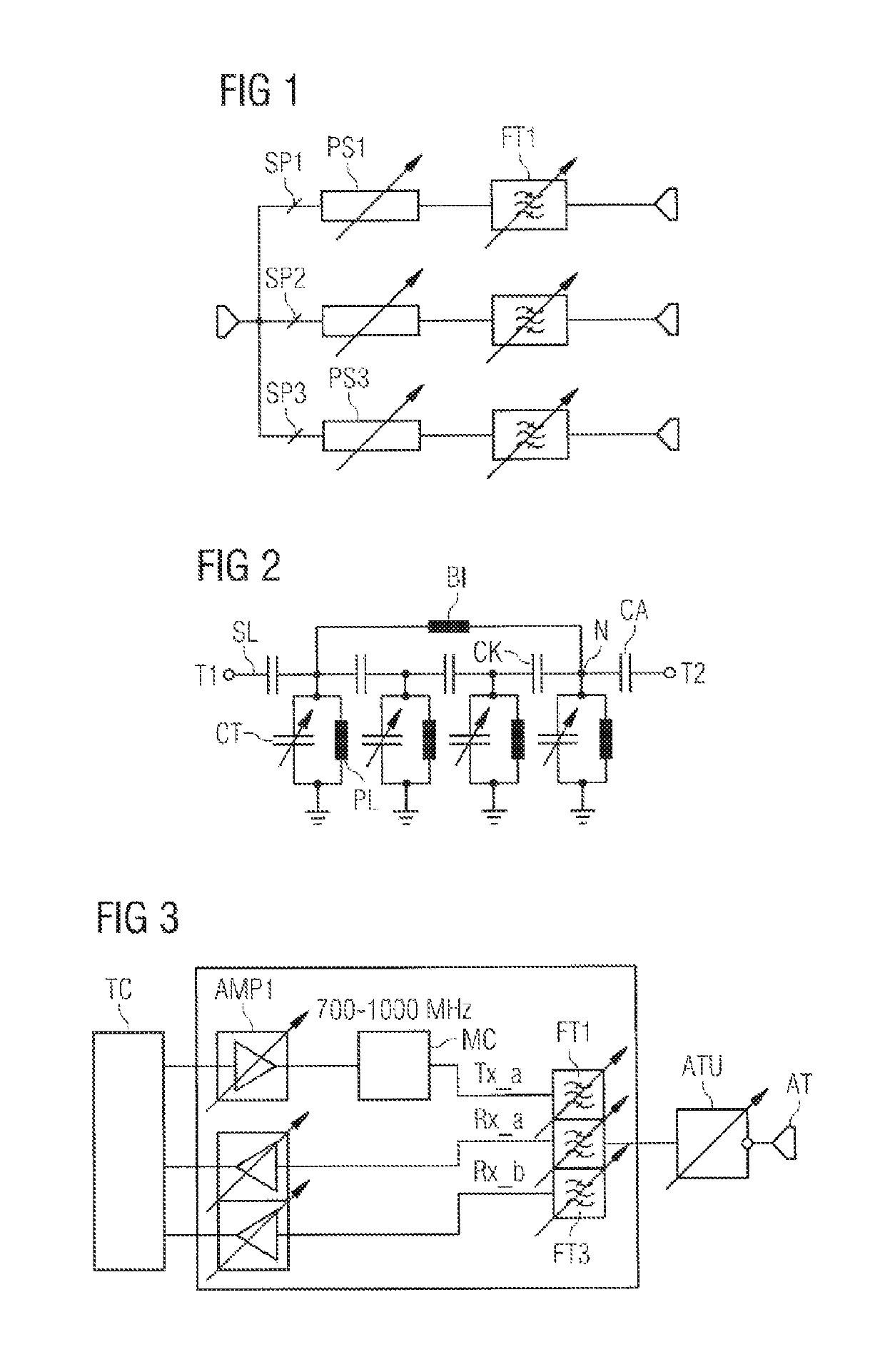
[0057]FIG. 1 shows the block diagram of a simple front-end circuit in which three signal paths SP1 to SP3 are connected to a common antenna connection AT. A tunable filter FT is arranged in each signal path SP. A phase shifter circuit PS1, PS2, PS3 which is tunable is additionally respectively arranged between the tunable filter and the antenna connection. The other ends of the signal paths SP which are opposite the antenna connection AT can be connected to one or more RF chips, for example a transceiver circuit. Each of the tunable filters FT is preferably in the form of a tunable bandpass filter. Each of the filters has a tuning range, the tuning ranges of the three filters illustrated being able to be identical.

[0058]FIG. 2 shows a possible embodiment of a tunable filter circuit FT. A serial signal line SL is connected between a first and a second connection T1, T2. The signal line has four circuit nodes N, to each of which a parallel branch to ground is connected. Each parallel ...


PUM


Abstract

A front end circuit is disclosed. In an embodiment, the circuit includes a first antenna connection and first to third signal paths, each of which include a tunable filter and each of which is connected to the first antenna connection. The circuit further includes at least one phase shifter arranged in at least one of the signal paths between a respective filter and the first antenna connection and a control circuit configured to tune frequency bands of the filters, wherein the filters are operable in a FDD operating mode or a TDD operating mode, and wherein the front-end circuit is simultaneous operable in at least one transmission band and at least one reception band using all three filters and the associated signal paths.

Description

[0001]This patent application is a national phase filing under section 371 of PCT / EP2014 / 061477, filed Jun. 3, 2014, which claims the priority of German patent application 10 2014 102 699.3, filed Feb. 28, 2014, each of which is incorporated herein by reference in its entirety.TECHNICAL FIELD[0002]The invention relates to a front-end circuit having a tunable filter, as can be used in wire-less communication devices, for example. It also relates to a front-end circuit which enables a carrier aggregation mode in which it is possible to transmit or receive in three transmission or reception bands at the same time.BACKGROUND[0003]Portable communication devices, WLAN routers etc. or more generally: transmission / reception devices which communicate using RF signals, require RF filters in order to separate desired signals from undesired signals. Such filters can be connected, for example, in front-end circuits, for example in duplexers.[0004]In this case, the front-end circuit should look a...

Claims


Application Information

Patent Timeline
Patent Type & Authority Patents(United States)
IPC IPC(8): H04B1/00H03H7/46H04L5/14H03H7/01
CPCH04B1/0057H03H7/465H04B1/0064H04L5/1461H03H2210/025H03H7/1708H03H7/1775
Inventor ELLA, JUHASCHMIDHAMMER, EDGAR
Owner SNAPTRACK
Why Eureka
Try Eureka