
Optical data transmission system and method

a transmission system and optical data technology, applied in the field of optical data transmission system and method, can solve the problems of non-linearity of leds (to be used for generating modulated light output), near zero, communication distortion, etc., and achieve the effect of improving the linearity of the relationship

Active Publication Date: 2021-09-02
SIGNIFY HLDG BV
View PDF5 Cites 2 Cited by
  • Summary
  • Abstract
  • Description
  • Claims
  • Application Information

AI Technical Summary

Benefits of technology

The patent describes a system that improves the fidelity of driving a light emitting component with a current. By avoiding a certain minimum current level, the system reduces distortion and increases the number of bits per symbol, resulting in a higher data rate that can be reliably communicated. The patent also notes that a DC offset can further improve the linearity of the drive current and light output relationship. These improvements can lead to better reproducibility of the signal at the receiver, where the functions of the modulator, converter, and offset unit can be combined into a single digital processing unit.

Problems solved by technology

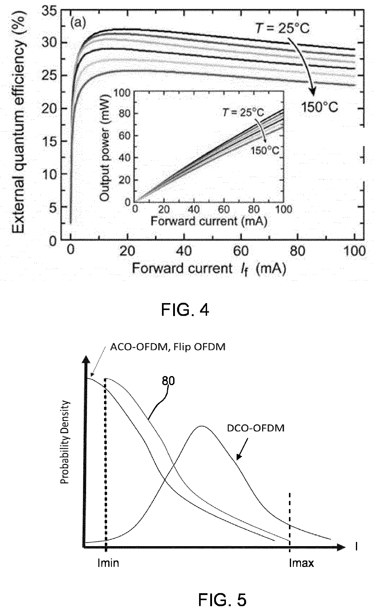
However, LEDs (to be used for generating the modulated light output) are very non-linear (in terms of their light intensity output versus drive current) near zero.
This means the communication is distorted.

Method used


Image

  • Optical data transmission system and method
  • Optical data transmission system and method
  • Optical data transmission system and method

Examples


Embodiment Construction

[0089]The invention will be described with reference to the Figures.

[0090]It should be understood that the detailed description and specific examples, while indicating exemplary embodiments of the apparatus, systems and methods, are intended for purposes of illustration only and are not intended to limit the scope of the invention. These and other features, aspects, and advantages of the apparatus, systems and methods of the present invention will become better understood from the following description, appended claims, and accompanying drawings. It should be understood that the Figures are merely schematic and are not drawn to scale. It should also be understood that the same reference numerals are used throughout the Figures to indicate the same or similar parts.

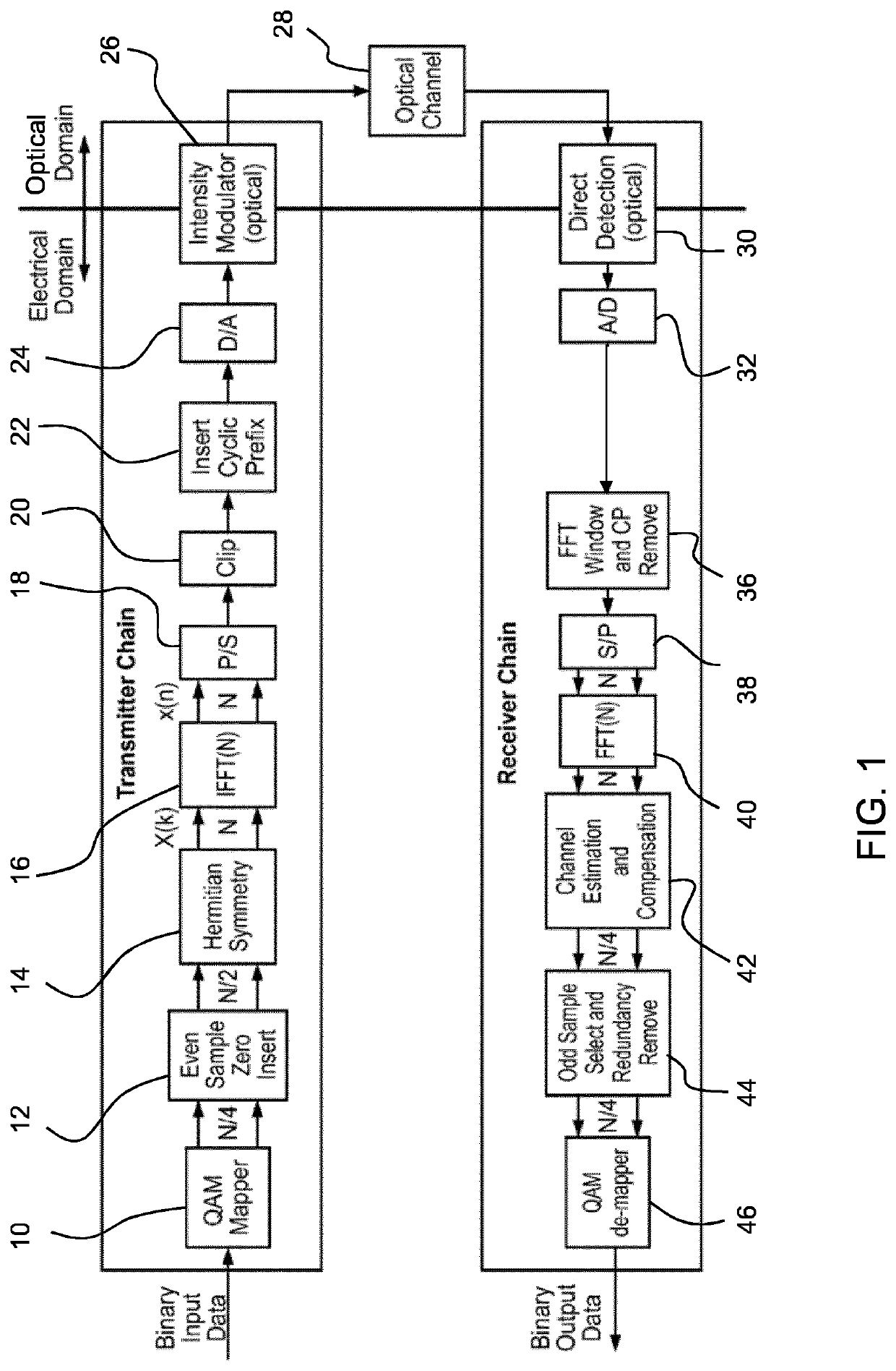
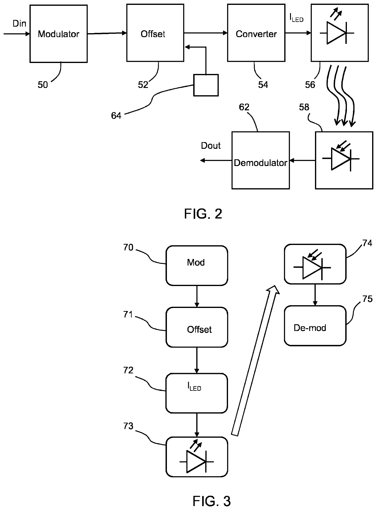
[0091]The invention provides an optical data transmission system and method which employs positive only data modulation, with an offset applied to the positive modulated values before generating modulated drive current sig...


PUM


Abstract

An optical data transmission system and method employs positive only data modulation, with an offset applied to the positive modulated values before generating modulated drive current signals for a light emitting component. The offset is such that the minimum drive current falls in a range where the electron-to-photon efficiency of the light emitting component is substantially constant. The drive current thus falls in a more linear part of its current vs. intensity characteristic. This reduces distortion and hence enables increased data rate.

Description

FIELD OF THE INVENTION[0001]This invention relates to an optical data transmission system and method.BACKGROUND OF THE INVENTION[0002]Non-coherent wireless communication methods are used for optical wireless communications. Properties such as frequency, amplitude, or intensity are used by the transmitter to send information.[0003]The need for higher data rates in wireless communication systems and the scarcity of available unlicensed bandwidth have fueled research into the use of spectrum outside of the RF band for wireless communication. Optical wireless communication such as UV, visible light, and infrared may provide a potential for very large unlicensed bandwidth that will satisfy the bandwidth needs for current and future wireless communication applications.[0004]Typically, first generation optical wireless communication systems may need to be non-coherent. This is due to the complexity and cost of coherent optical modulators capable of modifying the phase of the optical radiat...

Claims


Application Information

Patent Timeline
IPC IPC(8): H04B10/548H04B10/50H04B10/40
CPCH04B10/548H04B10/40H04B10/502H04B10/114H04B10/116
Inventor LINNARTZ, JOHAN-PAUL MARIE GERARD
Owner SIGNIFY HLDG BV
Learn More