Wavelength converter, light source apparatus, and projector

a technology of light source apparatus and wavelength converter, which is applied in the direction of lighting and heating apparatus, semiconductor devices of light sources, instruments, etc., can solve the problems of not meeting the requirements described above, dichroic film cannot be provided between the wavelength conversion layer and the light transmitting layer, etc., to achieve high-luminance video images, improve wavelength conversion efficiency, and improve reliability

Active Publication Date: 2019-11-12
SEIKO EPSON CORP
View PDF12 Cites 1 Cited by
  • Summary
  • Abstract
  • Description
  • Claims
  • Application Information

AI Technical Summary

Benefits of technology

[0004]An advantage of some aspects of the invention is to provide a wavelength converter that excels in ability to cool a wavelength conversion layer. Another advantage of some aspects of the invention is to provide a light source apparatus including the wavelength converter. Another advantage of some aspects of the invention is to provide a projector including the light source apparatus.

Problems solved by technology

However, no adhesive satisfies the requirements described above.
Further, since the wavelength conversion layer and the light transmitting layer are formed integrally with each other, the dichroic film cannot be provided between the wavelength conversion layer and the light transmitting layer.

Method used


Image

  • Wavelength converter, light source apparatus, and projector
  • Wavelength converter, light source apparatus, and projector
  • Wavelength converter, light source apparatus, and projector

Examples


first embodiment

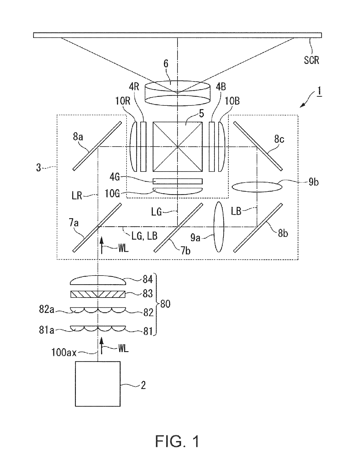
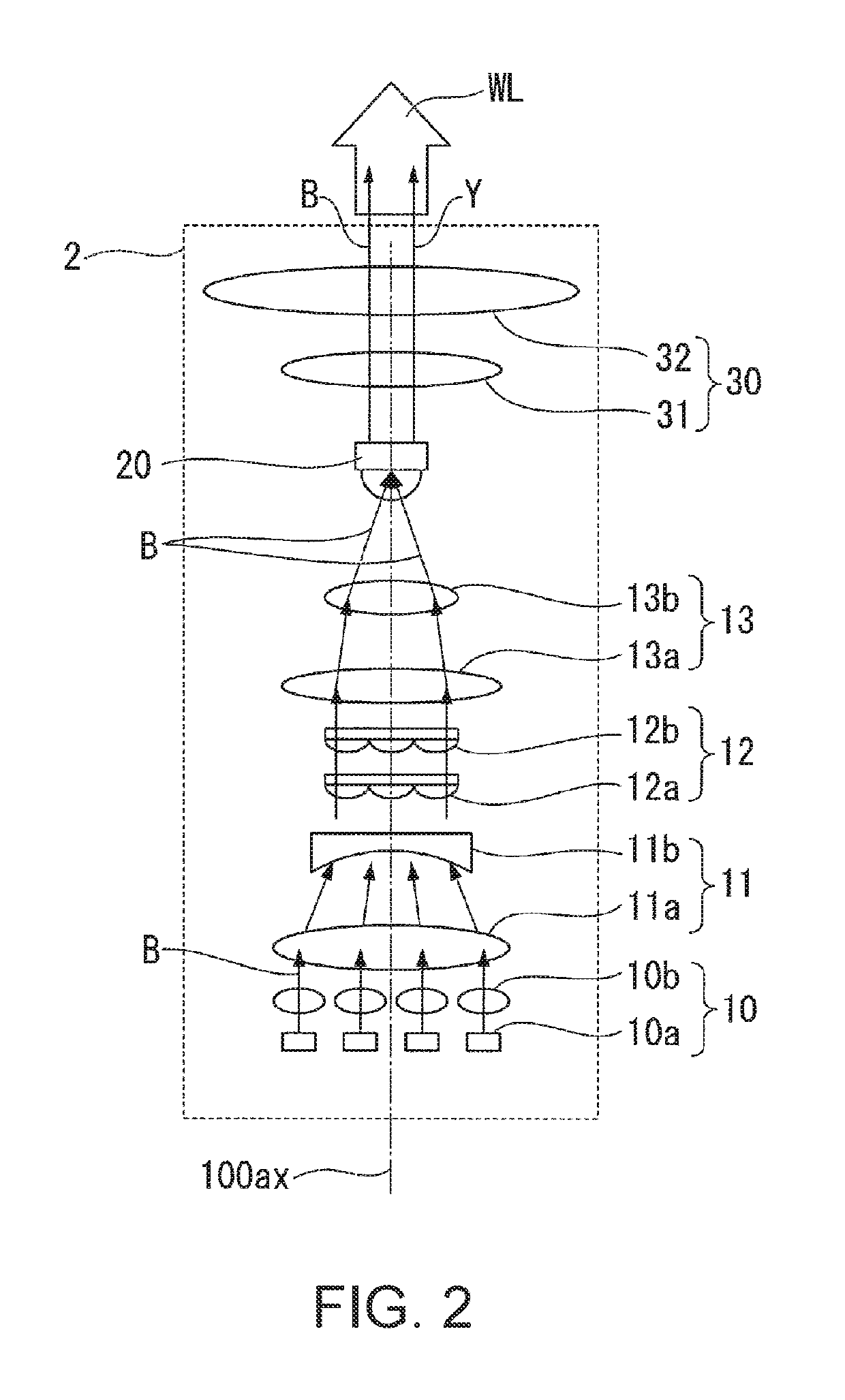
[0032]FIG. 1 shows a schematic configuration of a projector according to a first embodiment. FIG. 2 shows a schematic configuration of a light source apparatus.

[0033]A projector 1 according to the present embodiment is a projection-type image display apparatus that displays video images on a screen SCR, as shown in FIG. 1. The projector 1 includes a light source apparatus 2, a uniform illumination system 80, a color separation system 3, a light modulator 4R, a light modulator 4G, a light modulator 4B, a light combining system 5, and a projection optical apparatus 6.

[0034]In the present embodiment, the light source apparatus 2 shown in FIG. 2 outputs white illumination light WL, which is part of blue excitation light B emitted from a semiconductor laser but outputted without undergoing wavelength conversion combined with yellow fluorescence Y, which is produced by a wavelength converter 20, which performs wavelength conversion on the excitation light. The illumination light WL enters...

second embodiment

[0095]A light source apparatus according to a second embodiment of the invention will next be described.

[0096]The configuration of the light source apparatus according to the present embodiment, which will be described below, differs from the configuration in the first embodiment described above in that the yellow fluorescence produced in the wavelength converter is combined with blue light produced in an optical system different from the optical system to which the wavelength converter belongs to produce the white illumination light. Therefore, in the following description, the configuration of the light source apparatus will be described in detail, and portions common to the first and second embodiments will not be described. Further, in the drawings used in the following description, components common to those in the first embodiment have the same reference characters.

[0097]FIG. 4 shows the configuration of the light source apparatus according to the second embodiment.

[0098]A lig...


PUM


Abstract

A wavelength converter includes a wavelength conversion layer formed of a ceramic phosphor and having a light incident surface on which excitation light is incident and a light exiting surface which faces the light incident surface, a light transmitting layer formed integrally with the light incident surface of the wavelength conversion layer, and a light transmitting member provided on a side of the light transmitting layer that is the side on which the excitation light is incident. The light transmitting layer and the light transmitting member are bonded to each other with the aid of optical contact.

Description

BACKGROUND1. Technical Field[0001]The present invention relates to a wavelength converter, a light source apparatus, and a projector.2. Related Art[0002]For example, JP-A-2012-169049 discloses a light source apparatus including an excitation light source that radiates excitation light, an optical system that focuses the excitation light, a phosphor (wavelength conversion layer) that radiates fluorescence when excited with the focused excitation light, and a glass substrate on which the phosphor is formed. In the light source apparatus, to dissipate heat generated in the phosphor so that the phosphor is cooled, the phosphor is formed on one surface of the glass substrate, and a cooling mechanism formed of a heat sink is provided on the one surface of the glass substrate (surface on which excitation light is incident).[0003]In the light source apparatus described above, it is also conceivable to more efficiently cool the phosphor by providing a light transmitting member that excels in...

Claims


Application Information

Patent Timeline
Patent Type & Authority Patents(United States)
IPC IPC(8): G03B21/20G03B21/16F21K9/64
CPCG03B21/16G03B21/204G03B21/2013F21K9/64F21V29/50F21V9/30
Inventor AKIYAMA, KOICHI
Owner SEIKO EPSON CORP
Why Eureka
Try Eureka