
Casing structure with functionality of effective thermal management

a technology of effective thermal management and casing structure, which is applied in the direction of cooling/ventilation/heating modifications, instruments, and modifications by conduction heat transfer, etc. it can solve the problems of b>12/b>′ not being exhausted via air vents, reducing the heat dissipation efficiency of conventionally-used thermal solutions, and achieving low thermal conductivity. , the effect of low thermal conductivity

Pending Publication Date: 2022-06-09
ALMI MATERIALS TECH CO LTD
View PDF11 Cites 0 Cited by
  • Summary
  • Abstract
  • Description
  • Claims
  • Application Information

AI Technical Summary

Benefits of technology

The present invention provides a casing structure with effective thermal management for electronic devices. The casing structure includes a casing member, a low thermal conductivity medium, a second heat spreader, and a first heat spreader. The casing member has excellent thermal radiation ability, which allows the heat generated by the electronic device to be continuously dissipated to air through the outer surface of the casing member. This helps to control the temperature of the casing member and prevents discomfort or injury to the user. The technical effect of this invention is to provide effective thermal management for electronic devices through a casing structure that prevents overheating and discomfort to the user.

Problems solved by technology

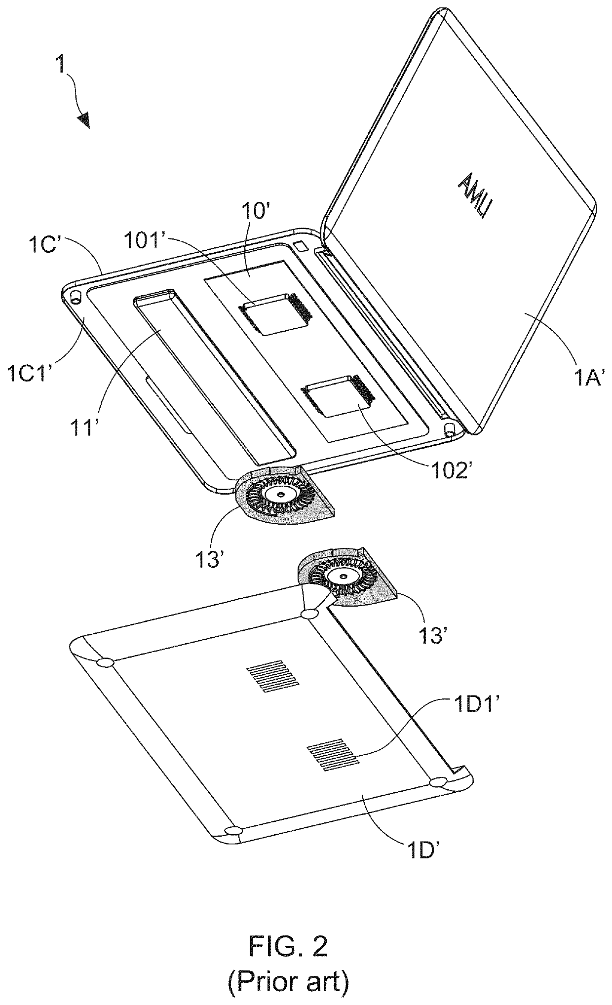
However, it is a pity that, the thermal isolation plate is also forms a thermal isolation between the base cover 1D′ and air, thereby not only leading the heat dissipation efficiency of the conventionally-used thermal solution to be largely reduced, but also causing the heat flow blew out by the radiating fans 12′ fail to be exhausted via the air vents 1D1′ of the base cover 1D′.

Method used


Image

  • Casing structure with functionality of effective thermal management
  • Casing structure with functionality of effective thermal management
  • Casing structure with functionality of effective thermal management

Examples


first embodiment

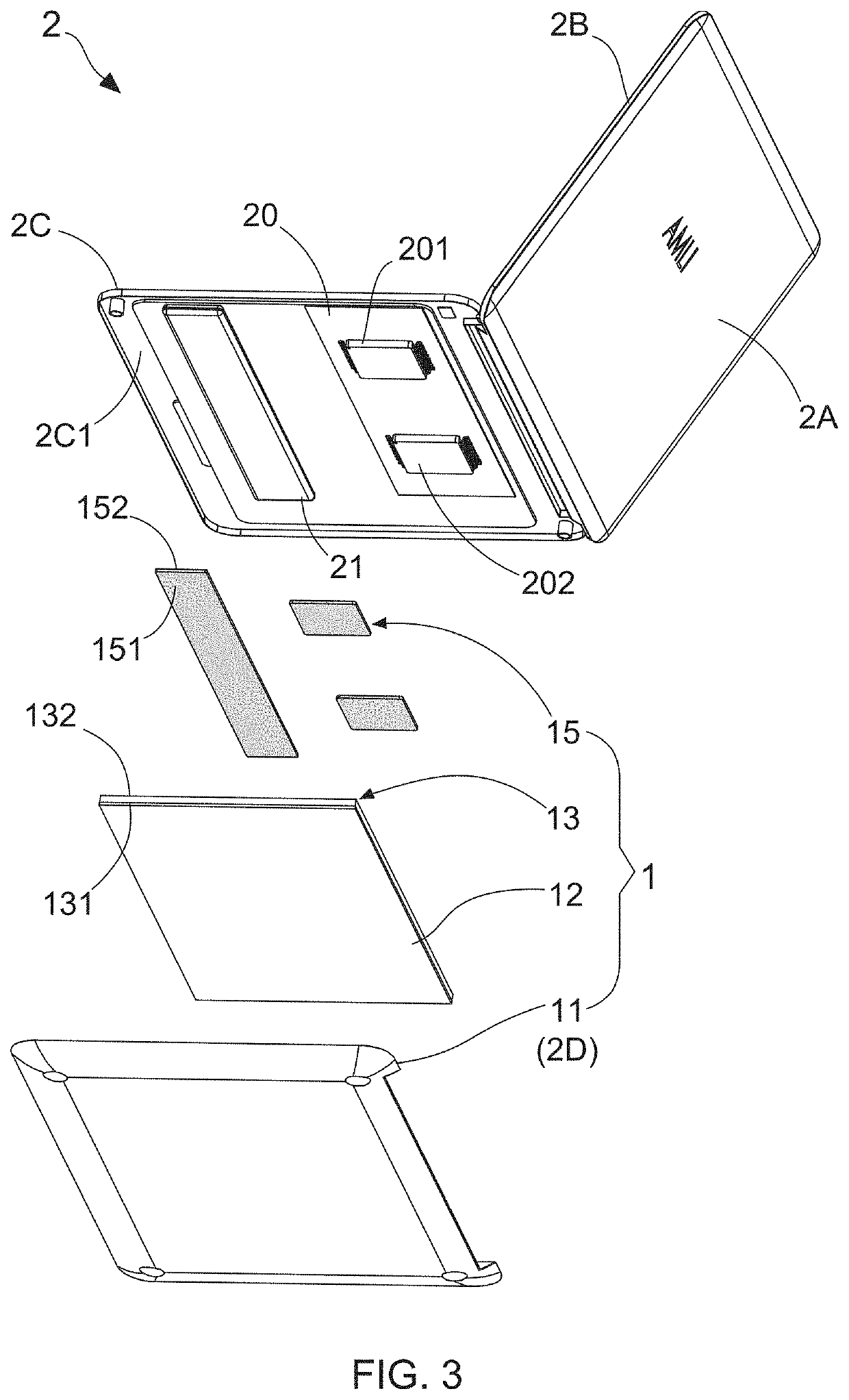
[0048]FIG. 3 shows one perspective stereo diagram of an electronic device that having a casing structure with functionality of effective thermal management according to the present invention, and FIG. 4 illustrates another one perspective stereo diagram of the electronic device that having the casing structure with functionality of effective thermal management according to the present invention. The present invention discloses a casing structure 1 with functionality of effective thermal management for being applied in an electronic device 2 by a form of a top casing and / or a back casing. For example, FIG. 3 and FIG. 4 depict that the electronic device 2 is a laptop computer comprising a first casing of a display device and a second casing of a host device. In which, the first casing consists of a rear cover 2A and a front panel 2B, and the second casing consists of a base cover 2D and a top cover 2C. From FIG. 3 and FIG. 4, it is found that a lithium battery 21 and a main board 20 p...

second embodiment

[0057]FIG. 8 shows one perspective stereo diagram of an electronic device that having a casing structure with functionality of effective thermal management according to the present invention, and FIG. 9 illustrates another one perspective stereo diagram of the electronic device that having the casing structure with functionality of effective thermal management according to the present invention. The present invention discloses a casing structure 1 with functionality of effective thermal management for being applied in an electronic device 2 by a form of a top casing and / or a back casing. For example, FIG. 8 and FIG. 9 depict that the electronic device 2 is a laptop computer comprising a first casing of a display device and a second casing of a host device. In which, the first casing consists of a rear cover 2A and a front panel 2B, and the second casing consists of a base cover 2D and a top cover 2C. From FIG. 8 and FIG. 9, it is found that a lithium battery 21 and a main board 20 p...

third embodiment

[0070]FIG. 13 shows one perspective stereo diagram of an electronic device that having a casing structure with functionality of effective thermal management according to the present invention, and FIG. 14 illustrates another one perspective stereo diagram of the electronic device that having the casing structure with functionality of effective thermal management according to the present invention. The present invention discloses a casing structure 1 with functionality of effective thermal management for being applied in an electronic device 2 by a form of a top casing and / or a back casing. For example, FIG. 13 and FIG. 14 depict that the electronic device 2 is a laptop computer comprising a first casing of a display device and a second casing of a host device. In which, the first casing consists of a rear cover 2A and a front panel 2B, and the second casing consists of a base cover 2D and a top cover 2C. From FIG. 13 and FIG. 14, it is found that a lithium battery 21 and a main boar...


PUM


Abstract

A casing structure with functionality of effective thermal management is disclosed, which consists of a casing member, a low thermal conductivity medium, a second heat spreader, and a first heat spreader. When a user operates the electronic device, heat generated from CPU and / or GPU is transferred to the second heat spreader via the first heat spreader, and then is two-dimensionally spread in the second heat spreader. Consequently, the heat is dissipated away from the casing member to air due to the outstanding thermal radiation ability of the casing member. The low thermal conductivity medium is adopted for controlling a heat transfer of heat transferring paths from the heat source and ends to the casing member. By applying the casing structure in an electronic device by a form of a top casing and / or a back casing, an outer surface temperature of the casing member can be well controlled.

Description

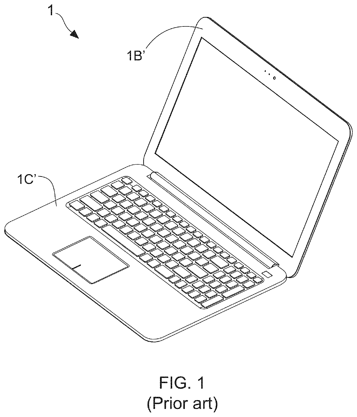
BACKGROUND OF THE INVENTION1. Field of the Invention[0001]The present invention relates to the technology field of thermal management for electronic device, and more particularly to a casing structure with functionality of effective thermal management.2. Description of the Prior Art[0002]Nowadays, portable electronic products have become necessary electronic devices for people in daily life and work, including laptop computer, tablet computer, smart phone, and wearable electronic device. FIG. 1 depicts a stereo diagram of a laptop computer, and FIG. 2 illustrates an exploded diagram of a portion of constituting elements of the laptop computer. The conventional laptop computer 1′ is known comprising a first casing of a display device and a second casing of a host device. In which, the first casing consists of a rear cover 1A′ and a front panel 1B′, and the second casing consists of a base cover 1D′ and a top cover 1C′. It is worth mentioning that, forgoing rear cover 1A′, front panel...

Claims


Application Information

Patent Timeline
Patent Type & Authority Applications(United States)
IPC IPC(8): H05K7/20G06F1/20
CPCH05K7/20445G06F1/203H05K7/20509G06F1/1616G06F1/1656G06F2200/201
Inventor HUANG, JIAN-JIALIN, CHUN-KAICHEN, CHIH-CHING
Owner ALMI MATERIALS TECH CO LTD
Learn More