Nuclear power plant containment cooling system and spray flow control method therefor

a technology of nuclear power plants and cooling systems, applied in nuclear elements, climate sustainability, greenhouse gas reduction, etc., can solve the problems of inconvenient mounting and maintenance damage to the structure of cooling liquid storage tanks, waste of cooling liquid, etc., to achieve simplified hardware structure, maximize utilization, and reduce the effect of cooling liquid volum

Active Publication Date: 2020-04-21
CHINA NUCLEAR POWER TECH RES INST CO LTD +1
View PDF6 Cites 0 Cited by
  • Summary
  • Abstract
  • Description
  • Claims
  • Application Information

AI Technical Summary

Benefits of technology

[0007]The objective of the present application is to provide a nuclear power plant containment cooling system and spray flow control method therefor, aiming at the drawbacks in the prior art that, it has a low safety, a complicated structure and is not conducive to. The system and method of the present application can passively and automatically adjust the flow of the cooling liquid.
[0045]When implementing the nuclear power plant containment cooling system and a spray flow control method therefor of the present application, the following advantageous can be achieved: by arranging a heat transfer liquid pool on the outside of the containment, the cooling liquid sprayed from the upper portion of the containment is stored; the opening degree of the spraying valve is automatically adjusted according to the rising and dropping of the liquid level of the heat transfer liquid pool, and the spray flow is in turn controlled. The cooling liquid which is not evaporated further flows downwardly into the heat transfer liquid pool, and is heated and evaporated in the heat transfer liquid pool. In this way, the cooling liquid still has the cooling function. Therefore, all the cooling liquid of the present application has its utilization maximized, and the volume of the cooling system liquid tank is obviously small. Furthermore, the present application only relies on the mechanical devices which do not need electrical controls, such as the buoyancy supporting element, the connecting rod devices, and the like, to automatically control the spray flow, without needing any sensors and corresponding temperature monitoring device which need power supply. In this way, the hardware structure is simplified, the cost is reduce, and the safety is also improved compared with the prior art.

Problems solved by technology

However, the above design has the following technical problems: when the water film has not been completely evaporated, the water in the storage tank of the cooling system will continuously flow downwardly, then reach to a bottom of the containment, and finally be directly discharged, which cause a waste of the cooling liquid.
Meanwhile, in order to ensure that the containment is sufficiently cooled, a cooling liquid storage tank having a relative large capacity (a relative heavy weight) is generally provided at the top of the containment, and the mounting and maintenance thereof are inconvenient.
It is likely for the structure of the cooling liquid storage tank to be damaged and for the safety function thereof to be disabled in case of coming across extreme events such as earthquake, tsunami, tornado and the like.
For the former one, if the flow is too large, lots of the cooling liquid is wasted since the cooling liquid can not be made the best use of.
For the later one, the operations for monitoring the temperature of the containment and controlling the flow of the cooling liquid need a support of the power source, which makes a design of the structure of the hardware more complicated; besides, when a lots of accidents occur, it is possible for the power source to be failed, and thus the cooling design described above cannot work normally.

Method used


Image

  • Nuclear power plant containment cooling system and spray flow control method therefor
  • Nuclear power plant containment cooling system and spray flow control method therefor
  • Nuclear power plant containment cooling system and spray flow control method therefor

Examples


Embodiment Construction

[0078]In order to make the objective, the technical solution and the advantages of the present application more clearly, the present application will be further described in detail with reference to the accompanying drawings and embodiments. It should be understood that, the specific embodiments described herein is only for explanation, and not for limitation.

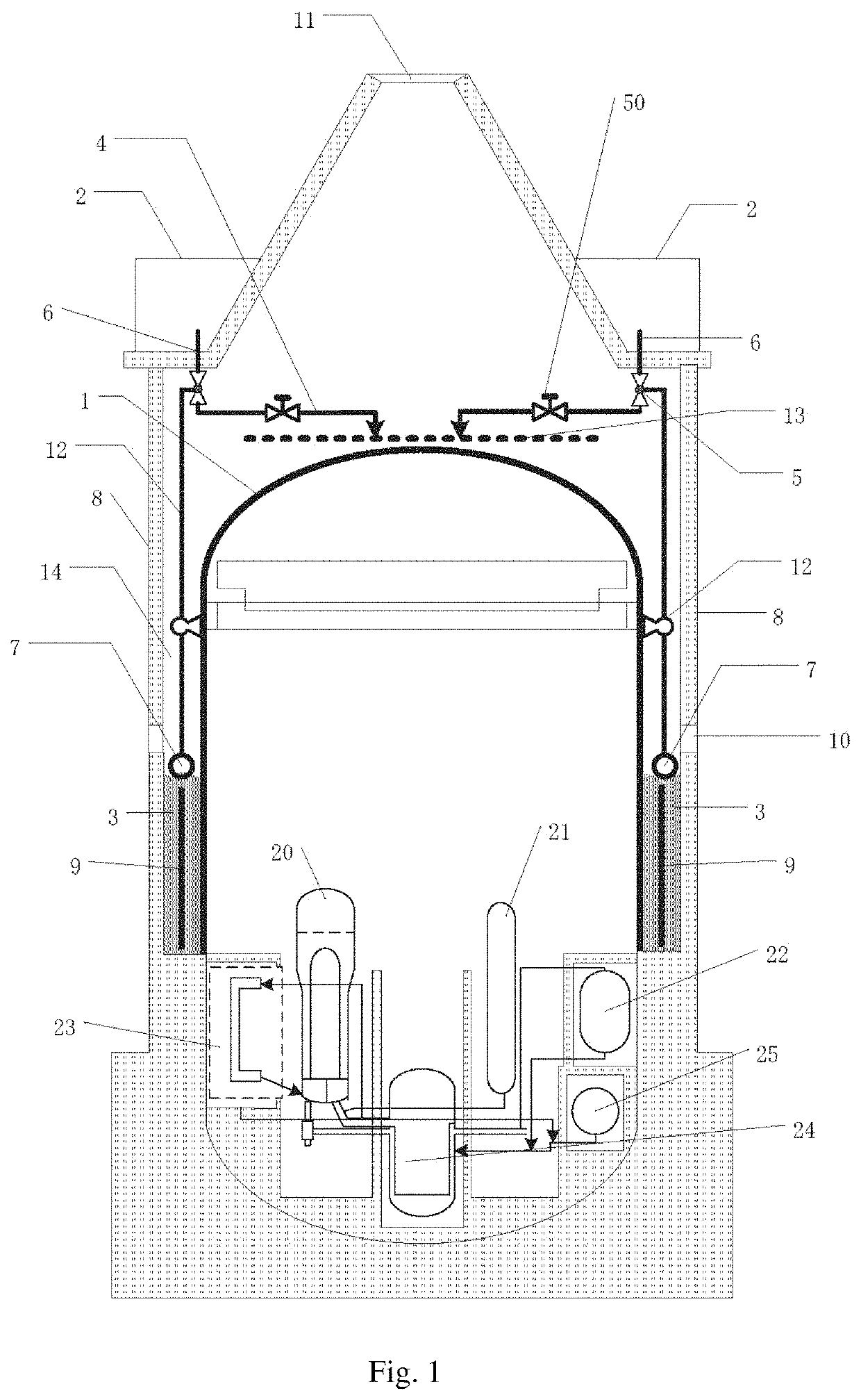
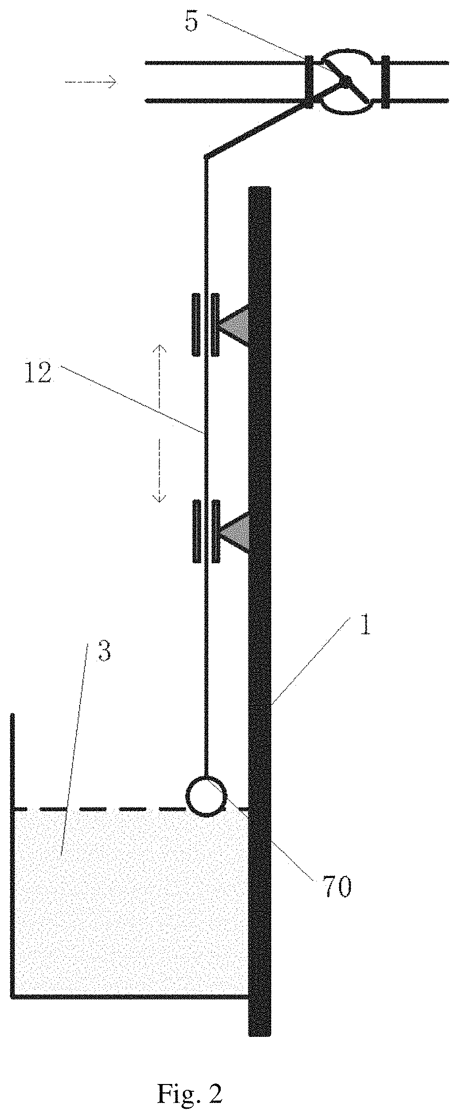
[0079]Aiming at the defects in the prior art that the containment cooling system has a low safety, a complicated structure and is not conducive to the promotion thereof, the present application designs a passive containment cooling system and method utilizing buoyancy to automatically adjust the spray flow. The system and spray flow control method of the present application can maximize the utilization of the cooling liquid. The containment cooling system and spray flow control method therefor of the present application can adjust the spray flow of the cooling liquid in time without any external power (such as electric power an...


PUM


Abstract

A nuclear power plant containment cooling system and a spray flow control method therefor. The system comprises a cooling system liquid tank (2) for storing cooling liquid, wherein the cooling system liquid tank (2) is provided at the top of a containment (1) and the cooling liquid is used for cooling the containment (1) through the gravity of the cooling liquid itself in the situation of an accident, and the cooling liquid is partially evaporated. The nuclear power plant containment cooling system further comprises an adjustment mechanism; wherein the adjustment mechanism is provided at a liquid outlet of the cooling system liquid tank (2), and the adjustment mechanism is used for controlling the flow at the liquid outlet according to buoyancy generated by a liquid level of the collected cooling liquid which is not evaporated.

Description

TECHNICAL FIELD[0001]The present application relates to a nuclear power plant containment cooling system therefor, and more particularly, relates to a passive nuclear power plant containment cooling system and a spray flow control method therefor.BACKGROUND[0002]A nuclear power plant usually uses a closed containment to contain reactors and several important safety systems, in order to prevent radioactive substances from leaking into the surrounding area in case an accident occurs in the nuclear power plant.[0003]If the nuclear power plant uses a safety cooling system based on the passive concept and a flow control system based on the automatic control principle, not only engineered safety features can be simplified, but also operator interventions can be reduced, and thus misoperation that may be produced can be reduced, and man-machine relationship can be improved, thereby improving the safety of the nuclear power plant.[0004]In an existing nuclear power system, in general, a cool...

Claims


Application Information

Patent Timeline
Patent Type & Authority Patents(United States)
IPC IPC(8): G21C15/18
CPCG21C15/18Y02E30/40Y02E30/30
Inventor YANG, JIANGWANG, TINGTAO, JUNCUI, JUNLU, XIANGHUISHANG, ZHENGFENGZHUANG, CHENGJUNLIN, WEIQINGLIN, JIANSHU
Owner CHINA NUCLEAR POWER TECH RES INST CO LTD
Why Eureka
Try Eureka