Air conditioner and its operating method

a technology of air conditioner and operating method, which is applied in the field of air conditioner, can solve the problems of disadvantageous restrictions in service conditions, inability to perform highly accurate temperature control of air conditioner, and inability to meet the requirements of application conditions, etc., and achieves the effect of high degree of accuracy and easy pre-operation of air temperature control

Active Publication Date: 2020-05-19
SHINWA CONTROLS
View PDF10 Cites 1 Cited by
  • Summary
  • Abstract
  • Description
  • Claims
  • Application Information

AI Technical Summary

Benefits of technology

[0004]An air conditioner of this type generally includes: a cooling unit in which a compressor, a condenser, an expansion value and a cooling coil are connected in this order by pipes in order to circulate a heating medium; and a heater. As the compressor of the cooling unit, a compressor that is driven at a constant revolving speed is used in general. This is because, due to the compressor that is driven at a constant revolving speed, a heating medium in the cooling unit can be basically circulated at a constant flow rate, whereby it is easy to preform an air temperature control with a high degree of accuracy.

Problems solved by technology

In addition, the cooling capacity can be varied by adjusting an opening of the expansion valve or the like, but its variable range is relatively small, and thus service conditions (application conditions) may be disadvantageously restricted.
However, since the cooling capacity varies in accordance with the variation of the operating frequency, the air conditioner is not suited for a highly accurate temperature control.

Method used


Image

  • Air conditioner and its operating method
  • Air conditioner and its operating method
  • Air conditioner and its operating method

Examples


Embodiment Construction

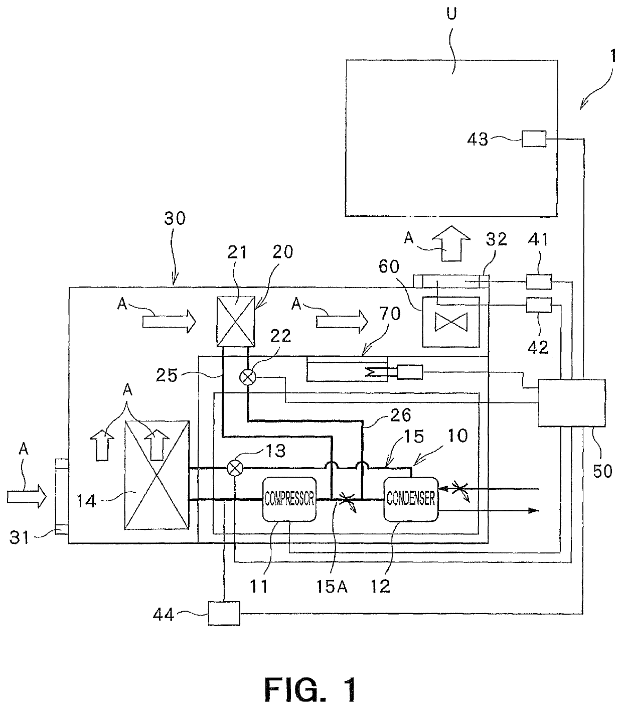
[0045]One embodiment of the present invention is described in detail below, with reference to the attached drawings. FIG. 1 is a schematic view of an air conditioner 1 according to the present invention. The air conditioner 1 in this embodiment is used to supply an apparatus for coating and developing a photoresist with air whose temperature is controlled, so as to maintain constant a temperature in the apparatus.

[0046]Firstly, a schematic structure of the air conditioner 1 in this embodiment is described.

[0047]As shown in FIG. 1, the air conditioner 1 includes: a cooling unit 10 in which a compressor 11 which is operated at a variable operating frequency so that a revolving speed thereof is adjustable, a condenser 12, an expansion valve 13 and a cooling coil 14 are connected in this order by pipes 15 in order to circulate a heating medium; a heating unit 20 which causes a part of the heating medium flowing out from the compressor 11 toward the condenser 12 to diverge, and causes it...


PUM


Abstract

An air conditioner includes: a cooling unit having a compressor operated at a variable operating frequency to adjust a revolving speed thereof, a condenser, an expansion valve and a cooling coil; and a heating unit for causing the heating medium flowing from the compressor toward the condenser to diverge, and to return to flow into the condenser, through a heating coil and a thermal dose adjusting valve disposed on the downstream side thereof; so as to control a temperature of air by the cooling and heating coils. When an opening manipulated variable of the thermal dose adjusting valve exceeds a first threshold value over a period of time, an operating frequency of the compressor is decreased, and when the opening manipulated variable of the thermal dose adjusting valve falls below a smaller, second threshold value, over the said period of time, the operating frequency of the compressor is increased.

Description

FIELD OF THE INVENTION[0001]The present invention relates to an air conditioner and its operating method.BACKGROUND ART[0002]An indoor temperature of a cleanroom in a semiconductor manufacturing plant is strictly managed by an air conditioner. For example, an indoor temperature of a clean room, in which an apparatus (such as coater) for coating and developing a photoresist is installed, is sometimes required to be controlled within an error range of between +0.05° C. and −0.05° C. relative to a target temperature. Various air conditioners suited for such a cleanroom have been conventionally proposed (see Patent Document 1, for example).[0003]Patent Document 1: 3P2013-108652ASUMMARY OF THE INVENTION[0004]An air conditioner of this type generally includes: a cooling unit in which a compressor, a condenser, an expansion value and a cooling coil are connected in this order by pipes in order to circulate a heating medium; and a heater. As the compressor of the cooling unit, a compressor ...

Claims


Application Information

Patent Timeline
Patent Type & Authority Patents(United States)
IPC IPC(8): F24F11/00F24F11/84F24F11/89F24F11/49F24F11/72F24F110/10F24F110/20F24F110/40F24F140/10
CPCF24F11/84F24F11/49F24F11/72F24F11/89F24F2140/10F25B2400/0405F25B2400/0403F24F2203/021F24F2110/20F25B2600/0253F24F2110/40F25B2600/2501F24F2110/10
Inventor IKEDA, YOSUKEFURUMOTO, HIDEAKIKOMORI, HIROFUMIISHIMATSU, TAKUYA
Owner SHINWA CONTROLS
Why Eureka
Try Eureka