Compliant b-tube for radiator applications

a technology of b-tubes and radiators, which is applied in the direction of tubular elements, heat exhanger fins, stationary conduit assemblies, etc., can solve the problems of b-tube construction, affecting durability, and formation of bending moments within each tube, so as to maximize the compliancy of the tube and promote fluid mixing.

Active Publication Date: 2020-10-13
HANON SYST
View PDF29 Cites 0 Cited by
  • Summary
  • Abstract
  • Description
  • Claims
  • Application Information

AI Technical Summary

Benefits of technology

[0007]Compatible and attuned with the present invention, a tube having a modified central reinforcing structure for maximizing a compliancy of the tube, promoting fluid mixing within the tube, and creating turbulence within the fluid passed by the tube has surprisingly been discovered.

Problems solved by technology

One potential issue faced by the traditional B-shaped flat tube construction occurs as a result of the effects of thermal cycling.
The repeated presence of varying characteristics within different portions of each of the tubes, such as varying temperatures experienced in different regions of each of the tubes, may lead to the formation of a bending moment within each of the tubes.
The formation of such bending moments may affect the durability of such tubes when exposed to extended periods of thermal cycling with varying temperatures experienced between the two flow channels of each of the tubes.
The added rigidity adjacent the central partitioning wall exacerbates the incidence of failure due to thermal cycling because the different portions of each of the tubes experiencing different degrees of thermal expansion are restricted from moving and deforming relative to each other during use of the heat exchanger.
The restricted motion may in some circumstances lead to increased bending moments or elevated stresses within portions of each of the tubes.
These elevated stresses can lead to permanent deformation or eventual failure of one or more of the tubes following extended use thereof.

Method used


Image

  • Compliant b-tube for radiator applications
  • Compliant b-tube for radiator applications
  • Compliant b-tube for radiator applications

Examples


Embodiment Construction

[0025]The following detailed description and appended drawings describe and illustrate various embodiments of the invention. The description and drawings serve to enable one skilled in the art to make and use the invention, and are not intended to limit the scope of the invention in any manner. In respect of the methods disclosed, the steps presented are exemplary in nature, and thus, the order of the steps is not necessary or critical.

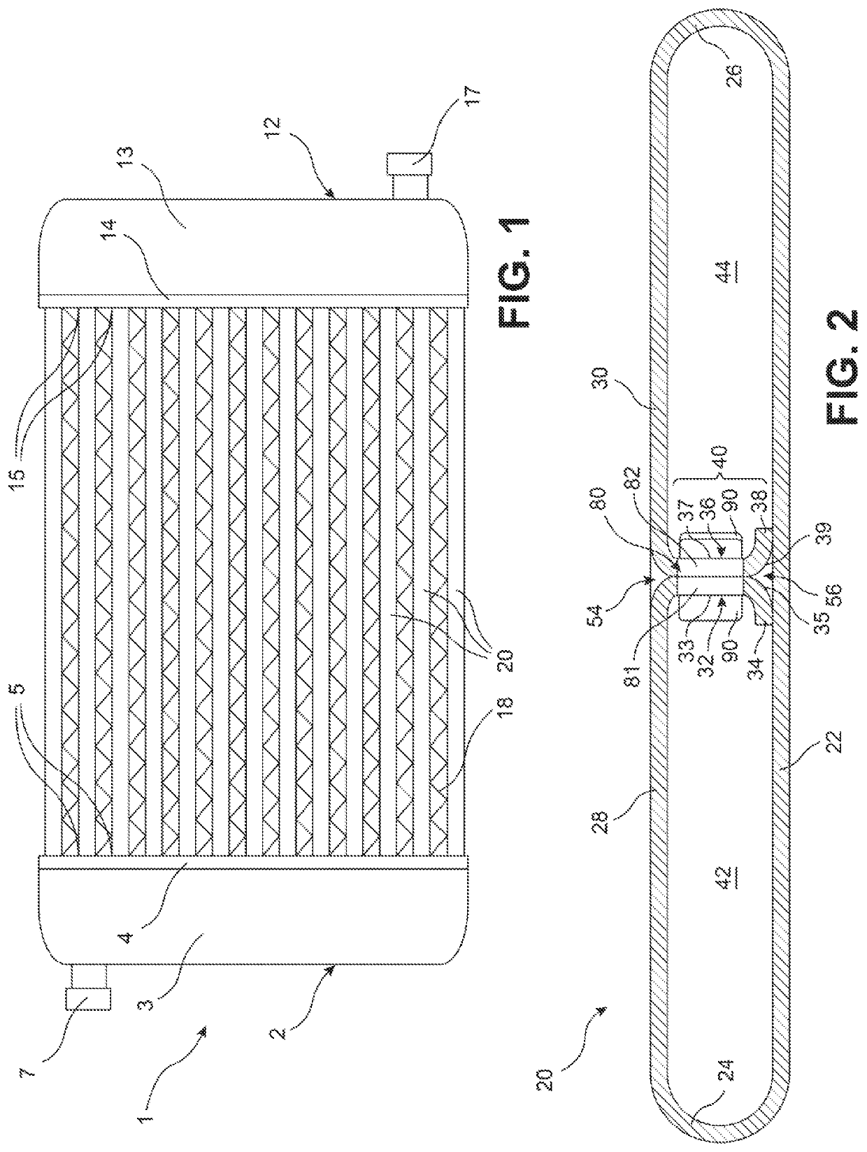
[0026]FIG. 1 illustrates a heat exchanger 1 according to an embodiment of the invention. The heat exchanger 1 may be used in an automotive application such as forming a portion of a heating, ventilating, and air conditioning (HVAC) system or a portion of a cooling system for regulating a temperature of one or more components of the automobile, as desired. The heat exchanger 1 may form an evaporator, a condenser, or a radiator of the motor vehicle, as non-limiting examples. The heat exchanger 1 may alternatively be used for any application requiring th...


PUM

PropertyMeasurementUnit
acute angleaaaaaaaaaa

Abstract

A tube for use in a heat exchanger including a base portion, an upper portion spaced from and opposing the base portion, and a partitioning wall extending between the base portion and the upper portion to divide a hollow interior of the tube into a first flow channel and a second flow channel. The partitioning wall includes a plurality of windows spaced from each other in a longitudinal direction of the tube to provide fluid communication between the first flow channel and the second flow channel. At least one of the windows includes a tabbed portion of the partitioning wall bent to extend into one of the first flow channel or the second flow channel.

Description

FIELD OF THE INVENTION[0001]The invention relates to a heat exchanger, and more specifically, to a heat exchanger including a B-shaped flat tube having a central partitioning wall with improved compliancy.BACKGROUND OF THE INVENTION[0002]Heat exchangers having folded flat tubes are well known in the art. Such heat exchangers typically include a plurality of the folded flat tubes spaced apart and arranged in parallel and extending between an inlet header tank and an outlet header tank. The inlet header tank receives a first fluid and distributes the first fluid between a plurality of flow channels formed within the flat tubes. The first fluid exchanges heat energy with a second fluid flowing through the spaces between adjacent ones of the flat tubes. After exchanging the heat energy within the flat tubes, the first fluid is recombined within the outlet header tank before exiting the heat exchanger.[0003]One common construction of a flat tube includes folding a sheet of metallic mater...

Claims


Application Information

Patent Timeline
Patent Type & Authority Patents(United States)
IPC IPC(8): F28D1/03B21C37/15F28F1/02
CPCF28F1/022F28D1/0391B21C37/155B21C37/151F28D1/05366F28F2250/04F28F2215/08B21C37/157F28F1/40F28D1/05383B21D53/06
Inventor DZIUBINSCHI, OREST ALEXANDRUSICKS, BRENNANSMITTERBERG, JAMESWHITLOW, GREG
Owner HANON SYST
Why Eureka
Try Eureka