Electrical connector

a technology of electrical connectors and connectors, applied in the direction of coupling contact members, coupling device connections, two-part coupling devices, etc., can solve the problems of high maintenance cost, damage to terminals or the insulating body, complicated process, etc., and achieve the effect of preventing improper operation and simplifying structure and configuration

Active Publication Date: 2021-04-06
ADVANCED CONNECTEK INC
View PDF19 Cites 1 Cited by
  • Summary
  • Abstract
  • Description
  • Claims
  • Application Information

AI Technical Summary

Benefits of technology

[0006]The disclosure provides an electrical connector that has a simplified structure and configuration and is capable of preventing improper operation.
[0021]Furthermore, the manufacturing process of the terminal having the first section and the branching second sections can be completed by using only one molding mold. In other words, in the manufacturing process of the terminals, the designer is not required to adopt different molding molds for different portions of the terminal. Accordingly, it is possible to effectively simplify the manufacturing technique and manufacturing cost of the terminals.

Problems solved by technology

However, in either case, the terminals or the insulating body may be damaged due to improper operation of the user or mis-insertion of other connectors in the process of use.
When damaged, the electrical receptacle connector generally needs to be disassembled from a host device (i.e., removing the electrical receptacle connector from the motherboard) to be further replaced or repaired, which results in a complicated process and high maintenance cost.
Such a process is complicated and the terminals require different pressing molds.
The process is complicated and requires high precision, so it is likely to have a higher defect rate, which thus affects the production efficiency and cost.

Method used


Image

  • Electrical connector
  • Electrical connector
  • Electrical connector

Examples


Embodiment Construction

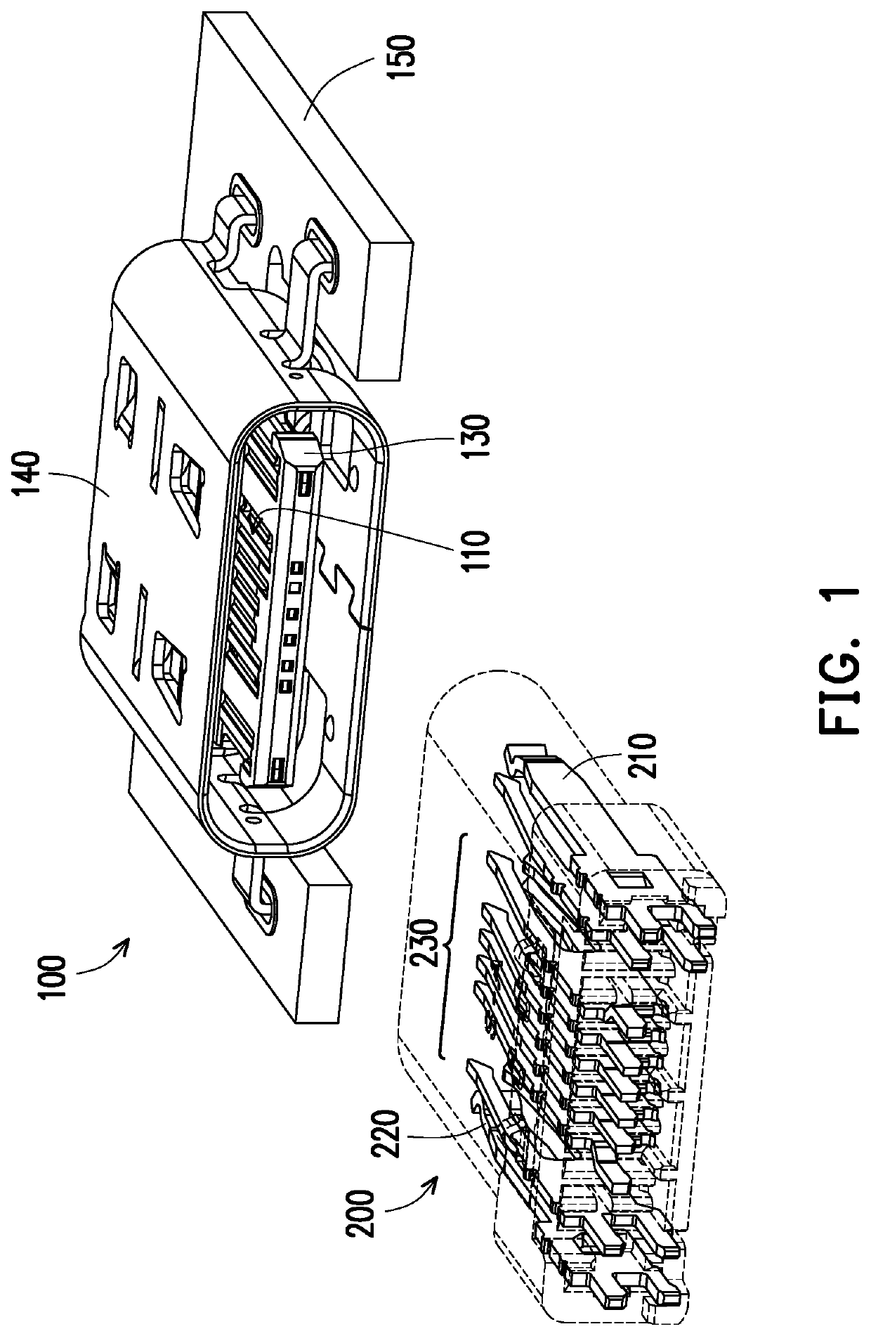
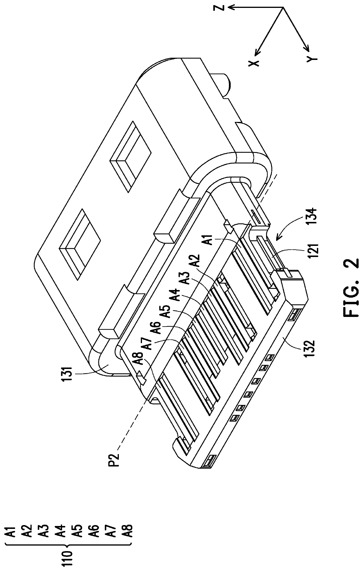
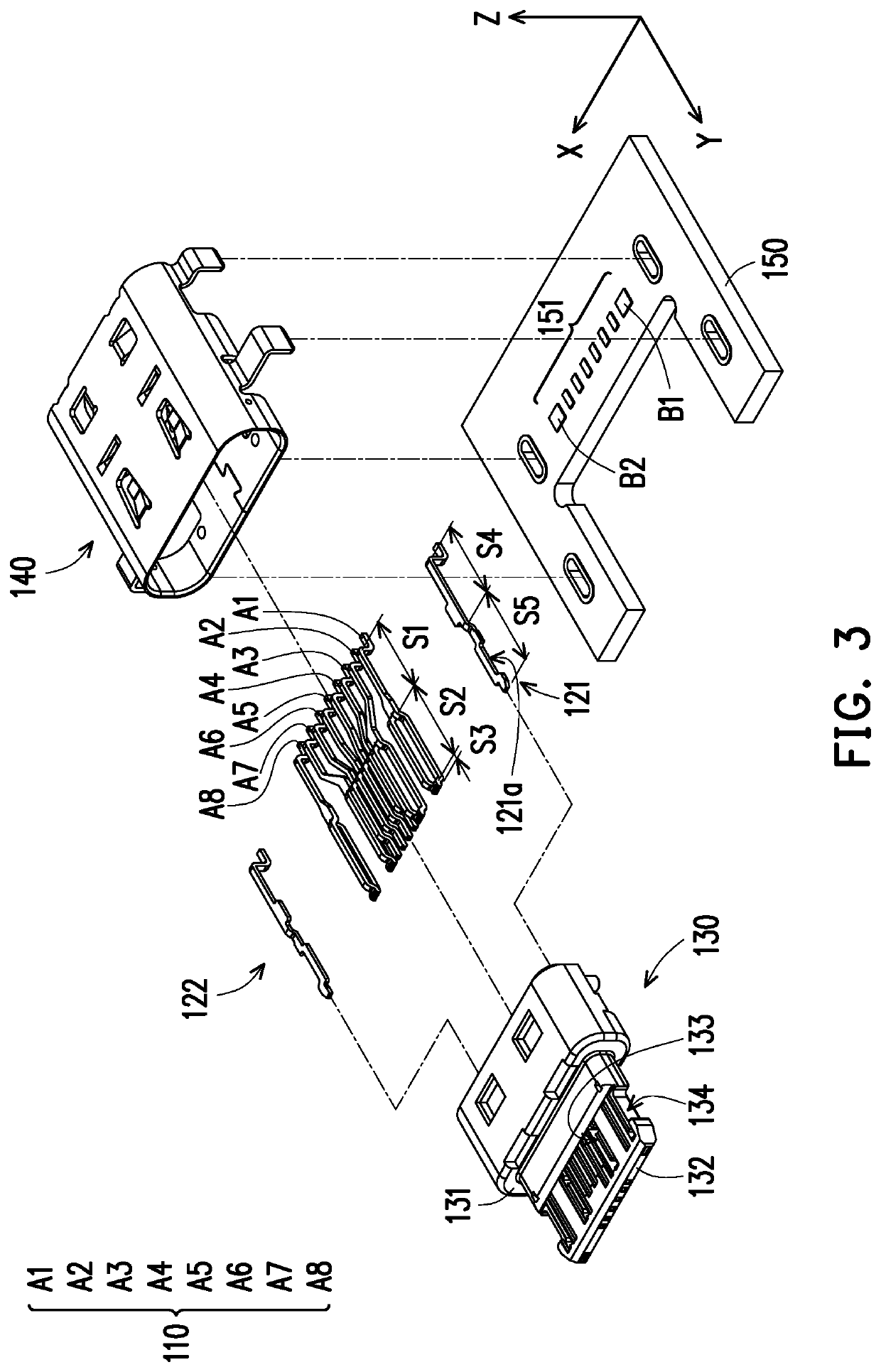
[0034]FIG. 1 is a schematic view of a pair of electrical connectors according to an embodiment of the disclosure. FIG. 2 is a schematic partial component view of one of the electrical connectors of FIG. 1. FIG. 3 is an exploded view of one of the electrical connectors of FIG. 1. Meanwhile, the disclosure also provides a Cartesian coordinate system X-Y-Z for convenience of component description. Referring to FIG. 1 to FIG. 3, in the embodiment, an electrical connector 100 (e.g., an electrical receptacle connector) is used to be mated with an electrical connector 200 (e.g., an electrical plug connector). The electrical connector 100 includes an insulating body 130, a terminal set 110, a pair of grounding members 121 and 122, a metallic shell 140, and a circuit board 150. The terminal set 110 is disposed in the insulating body 130, and after being combined together, the terminal set 110 and the insulating body 130 are enclosed by the metallic shell 140. Then, the metallic shell 140, al...


PUM


Abstract

An electrical connector including an insulating body and a plurality of terminals disposed in the insulating body is provided. At least one of the terminals has a first section and a pair of second sections. The second sections structurally extend and branch out from the first section. On a plane where the terminals are located, orthogonal projections of the second sections are misaligned and do not overlap with each other.

Description

CROSS-REFERENCE TO RELATED APPLICATION[0001]This application claims the priority benefit of China patent application serial no. 201810357294.1, filed on Apr. 20, 2018. The entirety of the above-mentioned patent application is hereby incorporated by reference herein and made a part of the specification.BACKGROUNDTechnical Field[0002]The disclosure relates to an electrical connector.Description of Related Art[0003]The Universal Serial Bus (USB) is commonly used by the general public and has developed from the USB 2.0 transmission specification to the current USB 3.0 transmission specification with a higher transmission rate. The appearance, structure, terminal contact mode, number of terminals, pitch between terminals, and pin assignment of terminals of the existing USB Type-C electrical connector are completely different from the current USB electrical connector. Generally, the current USB Type-C electrical receptacle connector includes a plurality of flat terminals disposed in an in...

Claims


Application Information

Patent Timeline
Patent Type & Authority Patents(United States)
IPC IPC(8): H01R12/55H01R12/72H01R13/405
CPCH01R12/727H01R12/55H01R13/405H01R12/7082H01R12/722H01R13/02H01R13/631H01R13/648H01R13/652H01R13/642H01R24/60
Inventor TSAI, YU-LUNHOU, PIN-YUANWANG, HSU-FENLI, KANG QINWANG, XI
Owner ADVANCED CONNECTEK INC
Why Eureka
Try Eureka