Burner igniting system for gas stove

a technology for igniting systems and gas stoves, which is applied in the direction of combustion processes, lighting and heating apparatus, combustion regulation, etc., can solve the problems of increasing manufacturing costs, and achieve the effect of preventing the burner igniting system from being easily damaged, reducing manufacturing costs, and simplifying the structure or configuration

Inactive Publication Date: 2014-09-18
AME LIGHTING
View PDF1 Cites 0 Cited by
  • Summary
  • Abstract
  • Description
  • Claims
  • Application Information

AI Technical Summary

Benefits of technology

[0008]The primary objective of the present invention is to provide a burner igniting system for a gas stove including a simplified structure or configuration having fewer parts or elements for effectively igniting the burner of the gas stove and for preventing the burner igniting system from being easily damaged.

Problems solved by technology

However, the typical igniting system includes a complicated structure or configuration that may include a complicated making or manufacturing procedure and that is required to be made or manufactured by specialized persons, and that may include a greatly increased manufacturing cost.

Method used


Image

  • Burner igniting system for gas stove
  • Burner igniting system for gas stove
  • Burner igniting system for gas stove

Examples


Embodiment Construction

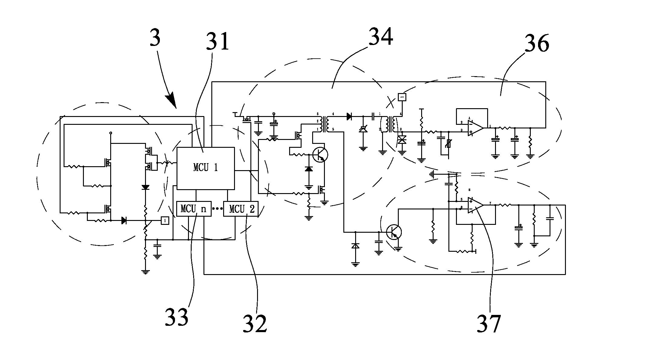
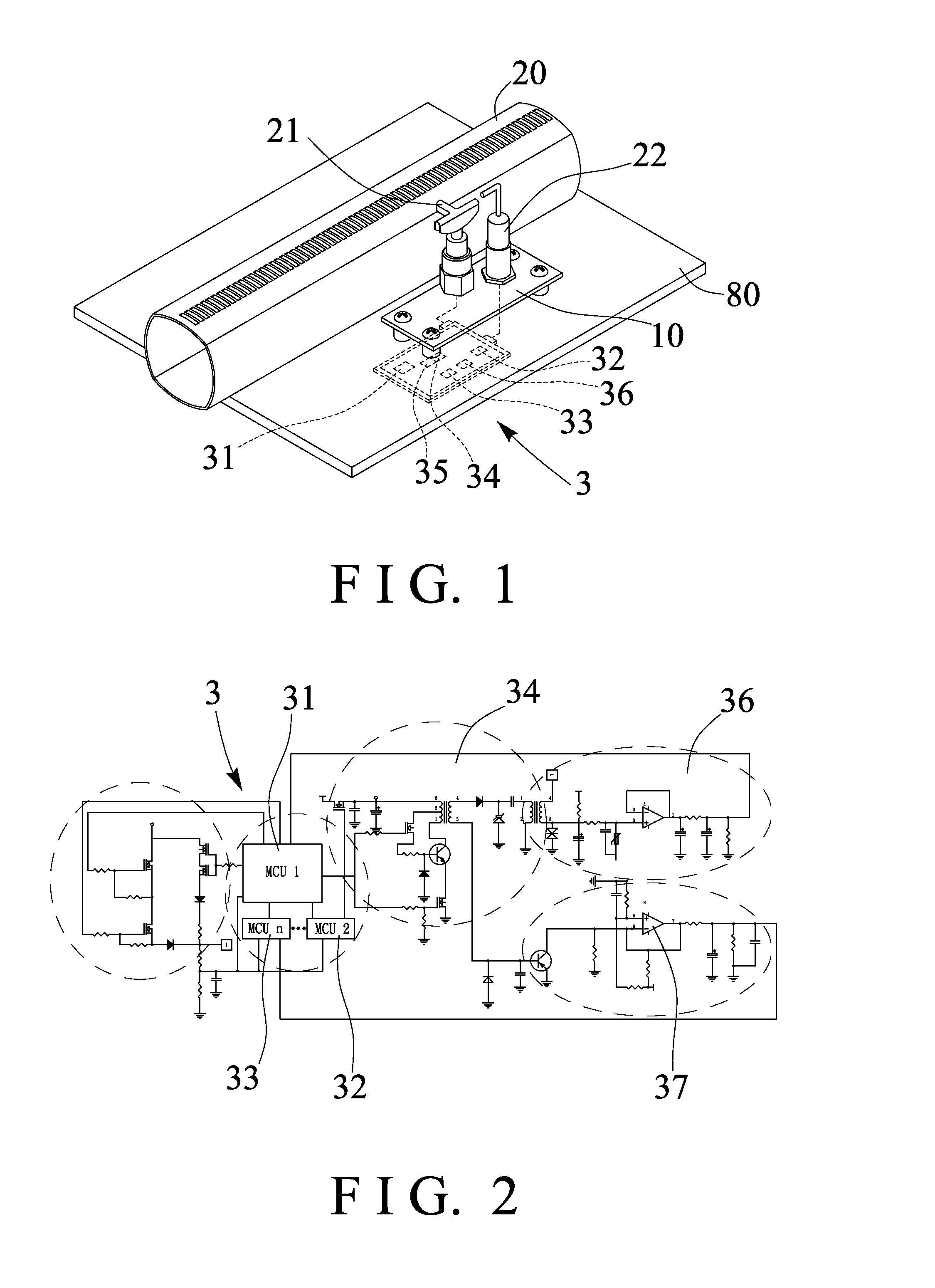
[0017]Referring to the drawings, and initially to FIG. 1, a burner igniting system in accordance with the present invention comprises a platform or base plate 10 disposed or attached or mounted or secured in a gas stove 80, in which the other parts or portions of the gas stove 80 are typical and are not related to the present invention and will not be described in further details and have not been shown or illustrated, a burner 20 disposed or attached or mounted or secured in the gas stove 80, a pilot light 21 disposed or attached or mounted or secured on the base plate 10 for supplying a flame to the burner 20, and an igniting and sensing device 22 also disposed or attached or mounted or secured on the base plate 10 for igniting the pilot light 21 and for sensing the presence of flame on the pilot light 21. It is to be noted that only the igniting and sensing device 22 is required to be provided for both igniting the pilot light 21 and sensing the presence of flame on the pilot lig...


PUM


Abstract

A burner igniting system includes a burner disposed in a gas stove, a pilot light disposed in the gas stove for supplying a flame to the burner, an igniting and sensing device disposed in the gas stove for igniting the pilot light and for sensing a presence of flame on the pilot light, and a control device includes two or more processing devices (MCU 1-n), a high voltage circuit electrically connected the processing devices (MCU 1-n) for being actuated by the processing devices (MCU 1-n), and the processing devices (MCU 1-n) and the high voltage circuit are electrically connected to the igniting and sensing device for actuating the igniting and sensing device to selectively ignite the burner with the pilot light.

Description

BACKGROUND OF THE INVENTION[0001]1. Field of the Invention[0002]The present invention relates to a burner igniting system for a gas stove, and more particularly to a burner igniting system for a gas stove including a simplified structure or configuration having fewer parts or elements for effectively igniting the burner of the gas stove and for preventing the burner igniting system from being easily damaged.[0003]2. Description of the Prior Art[0004]Typical igniting systems for igniting the burner of the gas stove comprise a spark generating circuit to produce sparks for igniting gas burners and a plurality of electrodes which are connected with the spark generating circuit for the ignition of the gas burners, a flame sensor circuit is operated in a first period for producing sparks, through of the electrodes, and in a second period and once the gas burner has been ignited, for sensing the presence of flame on each gas burner, and a reestablishing circuit, a current sensor circuit a...

Claims


Application Information

Patent Timeline
Patent Type & Authority Applications(United States)
IPC IPC(8): F23N5/12
CPCF23N5/123F23N2227/30F23N2227/36
Inventor LIAO, PEN LIANG
Owner AME LIGHTING
Why Eureka
Try Eureka