Electrical connector

a technology of electrical connectors and connectors, applied in the direction of coupling devices, two-part coupling devices, electrical apparatus, etc., can solve the problems of high maintenance cost, complex process, and difficulty in preventing damage to terminals or insulating bodies, so as to prevent improper operation and simplify structure and configuration

Active Publication Date: 2021-05-18
ADVANCED CONNECTEK INC
View PDF5 Cites 0 Cited by
  • Summary
  • Abstract
  • Description
  • Claims
  • Application Information

AI Technical Summary

Benefits of technology

[0006]The invention provides an electrical connector having a simplified structure and configuration, and is capable of preventing improper operation.
[0017]Based on the above, in the electrical connector according to the invention, at least one grounding terminal and the grounding member next to the grounding terminal form an integrally-molded structure, and along the arrangement direction of the terminals, a portion of the grounding terminal and a portion of the grounding member are misaligned from each other. In other words, the grounding terminal and the grounding member structure are integrally molded in the invention, so the manufacturing process may be effectively simplified. In other words, the grounding terminal and the grounding member may be manufactured by using a single mold set. Therefore, the manufacturing cost may be effectively reduced. Meanwhile, the portions where the grounding member and the grounding terminals are misaligned from each other are also the pressed portions when being connected with another electrical connector. Therefore, the pitch between terminals defined in relevant standards of the electrical connector is still met. Therefore, the electrical connector according to the embodiments of the invention exhibits desirable effects in design and manufacture under the premise that the required functional conditions are met.

Problems solved by technology

However, regardless of the structure, it is difficult to prevent damages to the terminals or the insulating body from mishandling or mistakenly inserting to other connectors by the user.
When damaged, the receptacle connectors often need to be disassembled from the entire device, such as removing from the receptacle connector from the motherboard, for further replacement or repair to take place, which results in a complicated process and high maintenance cost.
Such process is complicated and the terminals require different pressing molds.
The process is complicated and requires high precision, so it is likely to have a higher defect rate, which thus affects the production efficiency and cost.

Method used


Image

  • Electrical connector
  • Electrical connector
  • Electrical connector

Examples


Embodiment Construction

[0029]Reference will now be made in detail to the present embodiments of the invention, examples of which are illustrated in the accompanying drawings. Wherever possible, the same reference numbers are used in the drawings and the description to refer to the same or like parts.

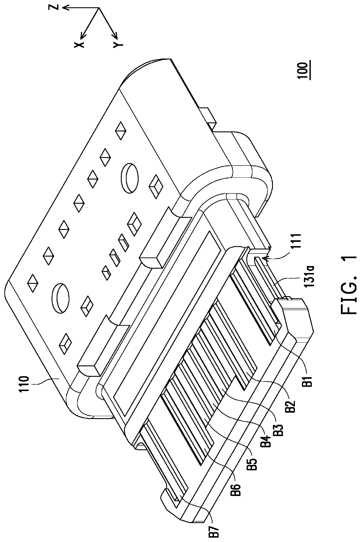
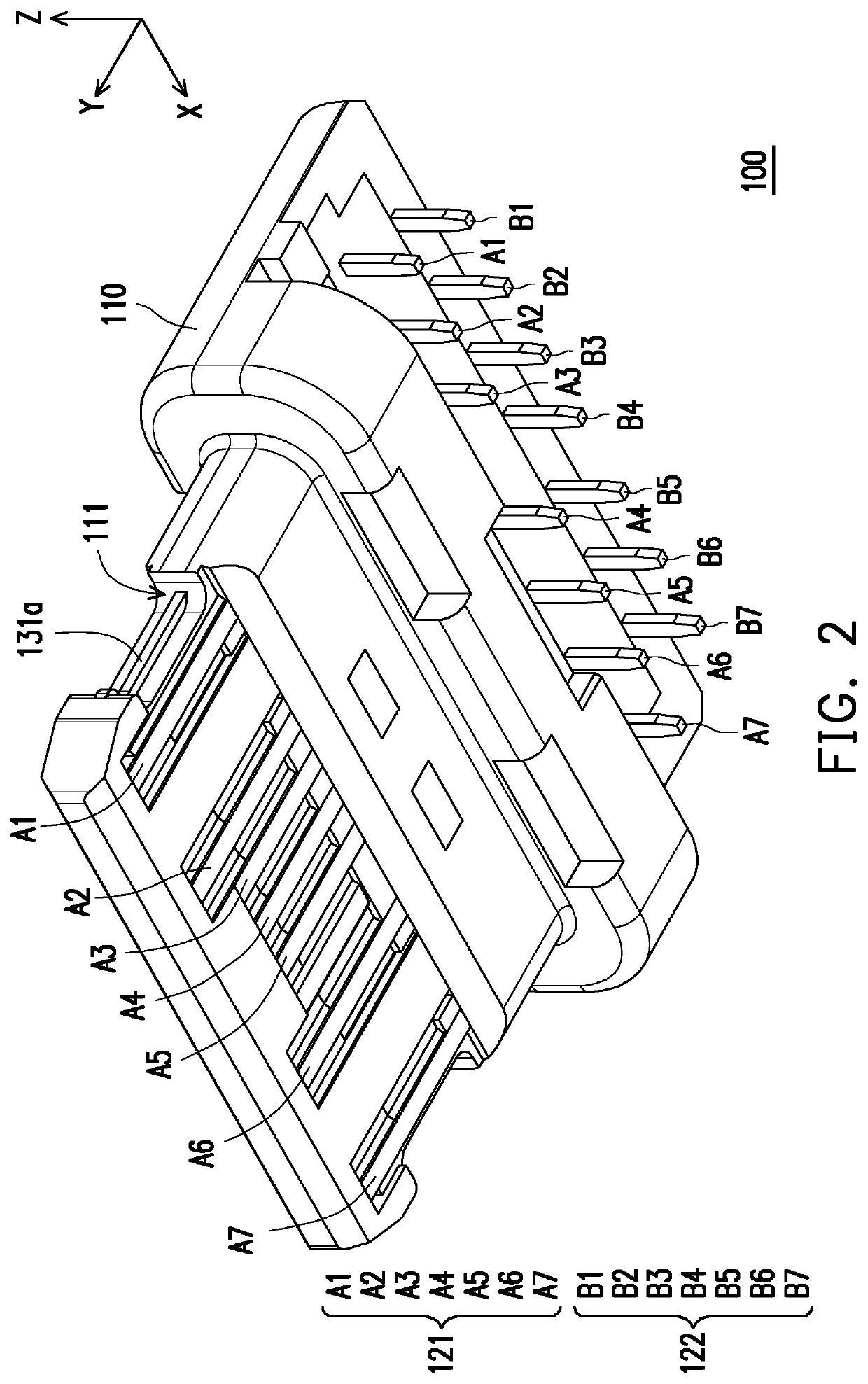
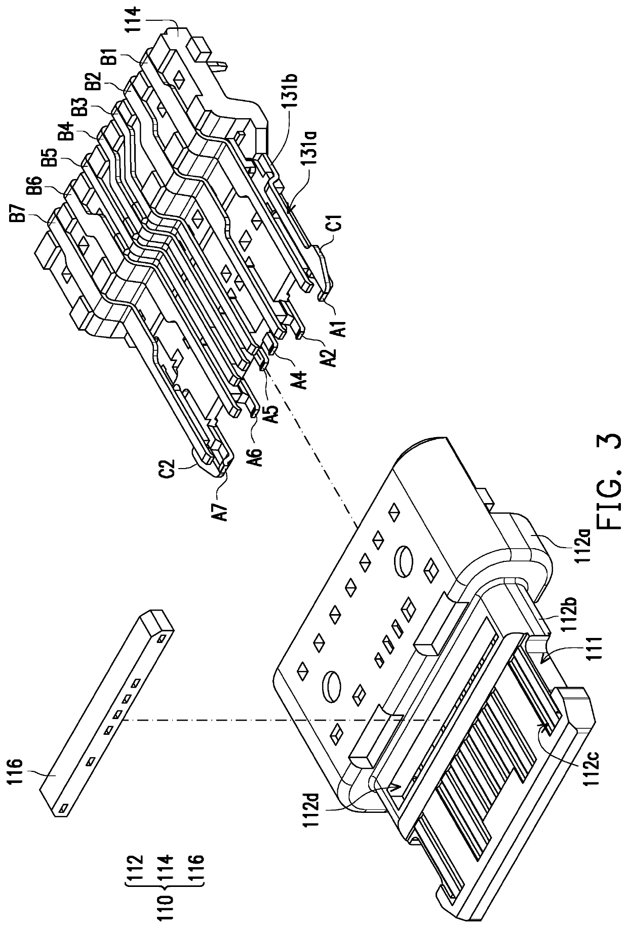
[0030]FIG. 1 is a schematic view of an electrical connector according to an embodiment of the invention. FIG. 2 is a schematic view of the electrical connector of FIG. 1 from another perspective. FIGS. 3 and 4 respectively illustrates exploded views of an electrical connector at different degrees. Here, a Cartesian coordinate system is provided for the ease of describing relevant components. Referring to FIGS. 1 to 4, in this embodiment, an electrical connector 100, such as a receptacle connector, includes an insulating body 110, a plurality of terminals Al to A7 and B1 to B7, and grounding members C1 and C2. The terminals A1 to A7 and B1 to B7 are disposed in the insulating body 110 by, for example, insert mo...


PUM


Abstract

An electrical connector including an insulating body, a plurality of terminals, and at least one grounding member is provided. The terminals and the grounding member are disposed in the insulating body. At least one grounding terminal among the terminals and the grounding member next to the grounding terminal form an integrally-molded structure. A portion of the grounding terminal and a portion of the grounding member are misaligned from each other along an arrangement direction of the terminals.

Description

CROSS-REFERENCE TO RELATED APPLICATION[0001]This application claims the priority benefit of China patent application serial no. 201810357316.4, filed on Apr. 20, 2018. The entirety of the above-mentioned patent application is hereby incorporated by reference herein and made a part of the specification.BACKGROUND OF THE INVENTION1. Field of the Invention[0002]The invention relates to an electrical connector.2. Description of Related Art[0003]Universal serial buses (USBs) are commonly used by the public and the transmission specification of USB has evolved from USB 2.0 to USB 3.0 that exhibits a higher transmission speed. The appearance, structure, contacting manner of terminals, number of terminals, pitch between respective terminals, and pin assignment of respective terminals of the conventional USB Type-C electrical connector are completely different from the current USB electrical connector. The conventional USB Type-C receptacle connectors generally include a plurality of elastic...

Claims


Application Information

Patent Timeline
Patent Type & Authority Patents(United States)
IPC IPC(8): H01R24/00H01R13/405H01R12/72H01R13/6581
CPCH01R13/405H01R12/724H01R13/6581H01R13/648H01R13/652H01R13/6597H01R43/24
Inventor TSAI, YU-LUNHOU, PIN-YUANWANG, HSU-FENLI, KANG QINWANG, XI
Owner ADVANCED CONNECTEK INC
Why Eureka
Try Eureka