Stent and method of use

a stent and ureter technology, applied in the field of stents, can solve the problems of back pressure on the kidney, patient suffering symptoms of renal colic, transient edematous blockage of the ureter, etc., and achieve the effects of preventing, or significantly reducing, stent induced symptoms, and inhibiting irritative symptoms

Active Publication Date: 2021-05-18
INNOVENTIONS LTD
View PDF7 Cites 0 Cited by
  • Summary
  • Abstract
  • Description
  • Claims
  • Application Information

AI Technical Summary

Benefits of technology

[0017]Embodiments of the present invention include urinary stents. These urinary stents include ends for deployment in the kidney and bladder, respectively, that are non-coplanar. The bladder end of the stent includes a luminary groove, covered by a sleeve of materials softer than the remainder of the stent, allowing urine at sufficient pressures to pass out from the stent, between the stent and the sleeve. The bladder end of the stent adapts its shape according to respiratory changes in the length of the stent. This shape change also prevents or reduces stent related pain.
[0025]Some embodiments of the present invention allow the bladder end of the Double-J and pigtail stents to change geometry during while deployed in the body, in response to movement of the kidneys with respect to the bladder during respiration.

Problems solved by technology

Such manipulations may cause a transient edematous blockage of the ureter.
Should a Double-J stent or pigtail stent not have been left in place, there would be a strong likelihood of the patient suffering symptoms of renal colic caused by the ureteric peristaltic contractions trying to drain the urine, and severe loin pain, and that blockage can cause back pressure on the kidney.
This back pressure, if left untreated, can eventually lead to damage of the kidney.
However, patient comfort improved minimally at best.
This mechanical irritation causes the urgency and frequency in urinating even when the bladder is not full.
Increase of the intrarenal pressure when the bladder pressure increases, during its filling and voiding, induces the pain.
This flank pain is caused by the inherent design flaws common in contemporary Double-J and pigtail stents.

Method used


Image

  • Stent and method of use
  • Stent and method of use
  • Stent and method of use

Examples


Embodiment Construction

[0107]Before explaining at least one embodiment of the invention in detail, it is to be understood that the invention is not necessarily limited in its application to the details of construction and the arrangement of the components and / or methods set forth in the following description and / or illustrated in the drawings and / or the Examples. The invention is capable of other embodiments or of being practiced or carried out in various ways.

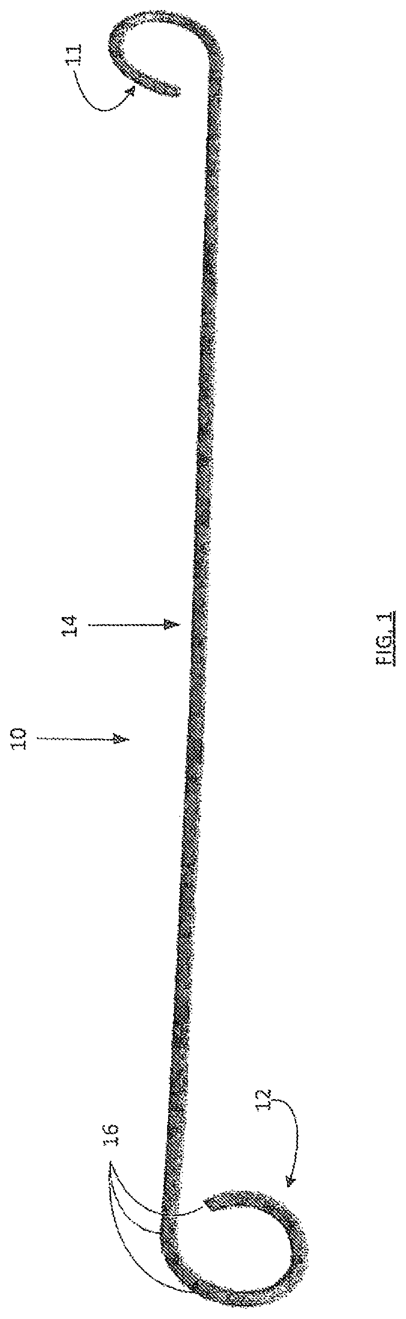
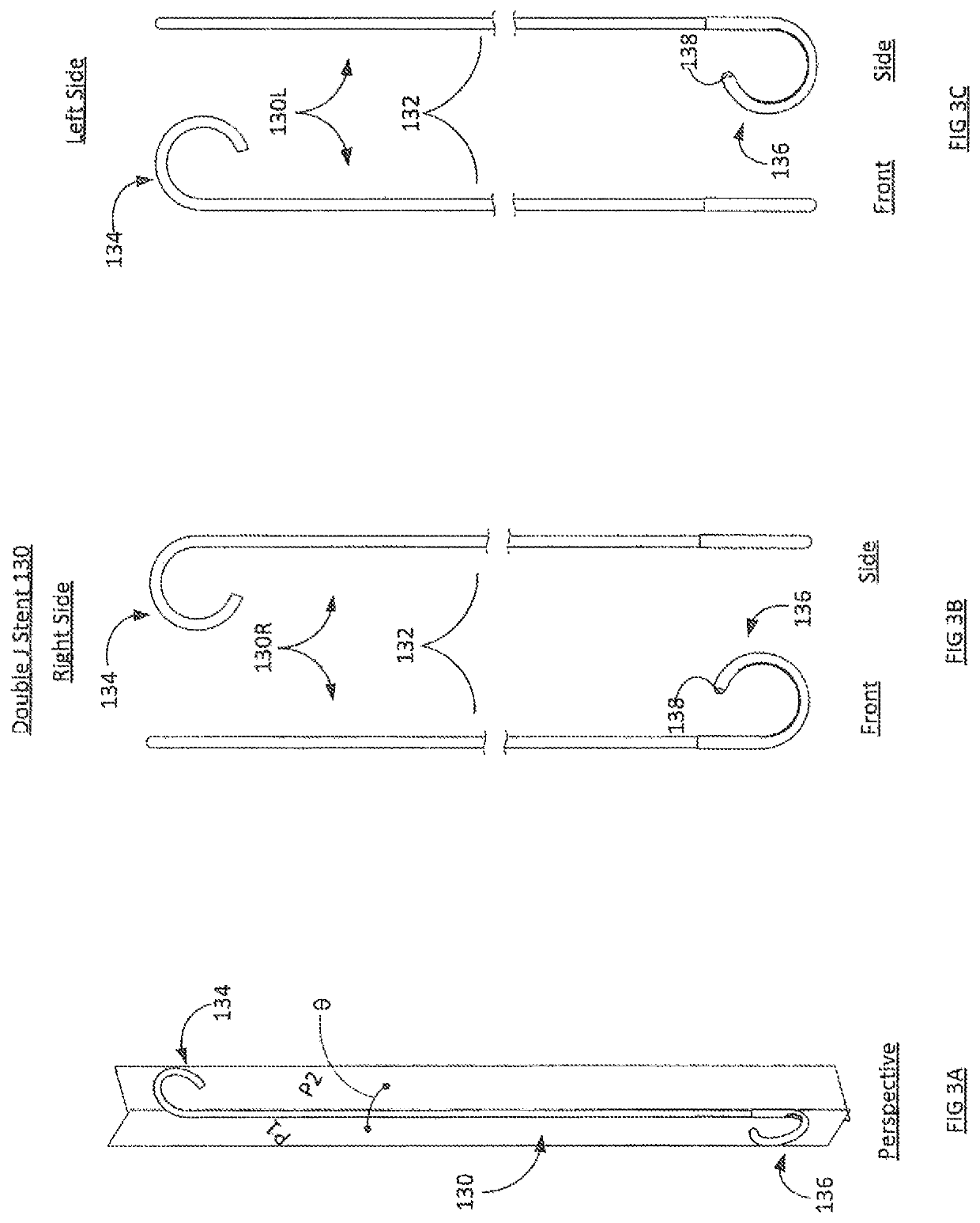
[0108]Attention is directed to FIGS. 3A-3C. FIG. 3A shows a perspective view of an apparatus or drainage device, for example, a Double-J stent 130 in accordance with embodiments of the present invention. The stent 130 may be either a right side stein (or right stent) 130R, as shown in FIG. 3B, for placement in the right ureter, or a left side stent (or left stent 130L), as shown in FIG. 3C for placement in the left ureter. Here, “left” and “right” area defined according to the corresponding “left” and “right” hands of the mammalian subject in whom t...


PUM


Abstract

A urinary stent includes ends for deployment in the kidney and bladder, respectively, that are non-coplanar. The bladder end of the stent includes a luminary groove, covered by a sleeve of materials softer than the remainder of the stent, allowing urine at sufficient pressures to pass out from the stent, between the stent and the sleeve. The bladder end of the stent adapts its shape according to respiratory changes in the length of the stent. This shape change also prevents or reduces stent related pain.

Description

CROSS REFERENCE TO RELATED APPLICATIONS[0001]This application is related to and claims priority from commonly owned U.S. Provisional Patent Application Ser. No. 62 / 164,049, entitled: Stent and Method of Use, filed on May 20, 2015, the disclosure of which is incorporated by reference herein in its entirety.FIELD AND BACKGROUND OF THE INVENTION[0002]The present invention, in some embodiments thereof, relates to urinary stents and, more particularly, but not exclusively, to stents used in, urologic or other applications.[0003]Ureteral stents, in particular stents known as Double-J stents and Pigtail stents, due to their J-shaped and pigtail ends, respectively, have been in common usage, to relieve ureteral obstructions, typically between the kidney and the bladder, for the past 40 plus years. Little has changed with these stents, since their development by Dr. Roy P. Finney in the 1970's.[0004]As shown in FIG. 1, a Double-J stent 10, exemplary of conventional Double-J stents and pigtai...

Claims


Application Information

Patent Timeline
Patent Type & Authority Patents(United States)
IPC IPC(8): A61F2/04A61M27/00A61B17/00
CPCA61F2/042A61M27/008A61B2017/00871A61F2002/048
Inventor YACHIA, DANIELPONOMARENKO, VALENTIN
Owner INNOVENTIONS LTD
Why Eureka
Try Eureka