Supercharge Your Innovation With Domain-Expert AI Agents!

Zinc-nickel composite plating bath, zinc-nickel composite plating film, mold and plating method

a zinc-nickel composite and bath technology, applied in the direction of manufacturing tools, foundry moulding apparatus, foundry patterns, etc., can solve the problems of inability to stably control the temperature of molds in some cases, method is not intended, and obstructed flow of coolant water, etc., to achieve excellent anti-corrosion properties, excellent hydrophilic properties, and improve the durability of the plating coating

Active Publication Date: 2021-08-03
HONDA MOTOR CO LTD
View PDF21 Cites 0 Cited by
  • Summary
  • Abstract
  • Description
  • Claims
  • Application Information

AI Technical Summary

Benefits of technology

[0005]A principal object of the present invention is to provide a zinc-nickel composite plating bath capable of preventing both of attachment of a sediment derived from calcium, bacterium, or the like and of a corrosion product generated due to corrosion.
[0030]In the plating method, it is preferred that the steel material is a mold and the surface to be plated is an inner surface of a coolant passage formed in the mold. In this case, thermal exchange via the coolant passage between the coolant water and the mold can be prevented from being inhibited by the corrosion product having a low thermal conductivity. Furthermore, even when the mold is continuously used, a flow rate of the coolant water in the coolant passage can be maintained in a good state. Thus, the temperature of the mold can be stably controlled for a long time, so that the mold can be maintained at an optimum temperature in a molding process, and the mold can be efficiently cooled after a molding process. In addition, the maintenance cycle of the mold can be prolonged.

Problems solved by technology

The washing method is not intended to remove the corrosion product generated by the corrosion of the inner surface of the coolant passage.
When the amount of the attached corrosion product is increased, the flow of the coolant water may be obstructed, and the mold temperature control cannot be stably performed in some cases.
Furthermore, when a high-temperature molding step and a mold cooling step are repeatedly carried out, a surface of the mold may be subjected to a thermal stress due to the thermal amplitude, and stress corrosion cracking may be caused in a corroded portion on the surface disadvantageously.

Method used


Image

  • Zinc-nickel composite plating bath, zinc-nickel composite plating film, mold and plating method
  • Zinc-nickel composite plating bath, zinc-nickel composite plating film, mold and plating method

Examples


Embodiment Construction

[0033]A preferred embodiment of the zinc-nickel composite plating bath, the zinc-nickel composite plating coating, the mold, and the plating method of the present invention will be described in detail below with reference to the accompanying drawings.

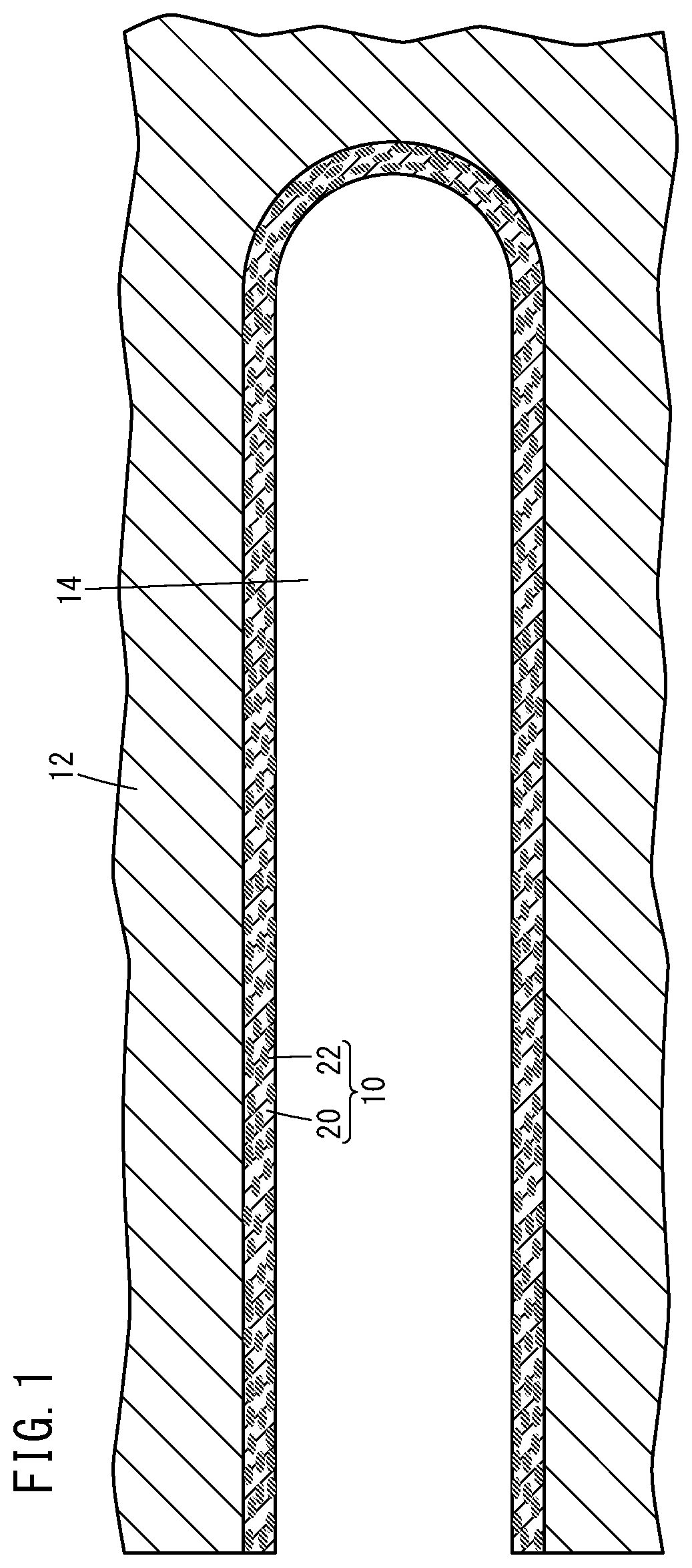
[0034]As shown in FIG. 1, a mold 12 has a bottomed hole of a coolant passage 14, and a zinc-nickel composite plating coating 10 according to this embodiment (hereinafter referred to simply as the plating coating 10) is formed on an inner surface of the coolant passage 14.

[0035]Specifically, the mold 12 is intended to be used for casting, injection molding, or the like. For example, the coolant passage 14 is formed in a wall in the vicinity of a cavity (not shown), and a coolant water is circulated through the coolant passage 14. The mold 12 contains a steel material such as SKD61.

[0036]The plating coating 10 is a composite plating layer containing a matrix 20 and silicon dioxide particles 22. The matrix 20 contains a zinc-nickel alloy, ...


PUM

PropertyMeasurementUnit
pHaaaaaaaaaa
pHaaaaaaaaaa
temperatureaaaaaaaaaa

Abstract

This zinc-nickel composite plating bath contains a zinc source, a nickel source, silicon dioxide particles and an ammonium-based dispersant in such ranges that enable the achievement of a zinc-nickel composite plating film wherein the codeposition amount of nickel is 10-16 wt % and the codeposition amount of the silicon dioxide particles is 7 vol % or more. Meanwhile, the pH of this zinc-nickel composite plating bath is 5.6 to 6.8.

Description

TECHNICAL FIELD[0001]The present invention relates to a zinc-nickel composite plating coating (film) containing a co-deposited silicon dioxide particle, a zinc-nickel composite plating bath for forming the coating, a mold having the coating on an inner surface of a coolant passage, and a plating method for forming the coating.BACKGROUND ART[0002]In a mold for casting, injection molding, or the like, a coolant passage for a coolant water is formed to control the temperature of the mold. For example, by supplying the coolant water through the coolant passage, the mold can be maintained at an optimum temperature in a molding process, and the mold can be efficiently cooled after a molding process. In a case where the coolant passage is in contact with the coolant water for a longer time, a larger amount of a corrosion product or a sediment derived from calcium or bacterium in the coolant water is attached to the coolant passage. In this case, because the corrosion product has a low ther...

Claims


Application Information

Patent Timeline
Patent Type & Authority Patents(United States)
IPC IPC(8): C25D3/56C25D5/36C25D15/00C25D7/00C25D7/04B22D17/22B22C9/06
CPCC25D3/565B22C9/06B22D17/22C25D5/36C25D7/00C25D7/04C25D15/00
Inventor FURUKAWA, YUKIOGAWA, YOSHIMITSUYAMANAKA, MASAHIRO
Owner HONDA MOTOR CO LTD
Features
  • R&D
  • Intellectual Property
  • Life Sciences
  • Materials
  • Tech Scout
  • Unparalleled Data Quality
  • Higher Quality Content
  • 60% Fewer Hallucinations
Learn More