Method and active antenna system in telecommunication networks

a technology of telecommunication network and active antenna, applied in the direction of antenna details, antenna monitoring, receivers, etc., can solve the problems of inability to test and calibrate each transceiver branch in such an aas, inability to meet the needs of the customer, so as to achieve the effect of alleviating, reducing, or eliminating at leas

Active Publication Date: 2022-03-15
TELEFON AB LM ERICSSON (PUBL)
View PDF10 Cites 0 Cited by
  • Summary
  • Abstract
  • Description
  • Claims
  • Application Information

AI Technical Summary

Benefits of technology

[0006]It is an objective of the present disclosure to provide a method and an active antenna system, AAS, which mitigate, alleviate, or eliminate at least some of the above named disadvantages.

Problems solved by technology

Testing and calibrating each transceiver branch in such an AAS will take more and more time due to the increased number of transceiver branches.
Further, transceiver branches in base stations, as any other component, inevitably suffer from a certain fail rate.

Method used


Image

  • Method and active antenna system in telecommunication networks
  • Method and active antenna system in telecommunication networks
  • Method and active antenna system in telecommunication networks

Examples


Embodiment Construction

[0029]It should be emphasized that the term “comprises / comprising” when used in this specification is taken to specify the presence of stated features, integers, steps, or components, but does not preclude the presence or addition of one or more other features, integers, steps, components, or groups thereof. As used herein, the singular forms “a”, “an” and “the” are intended to include the plural forms as well, unless the context clearly indicates otherwise.

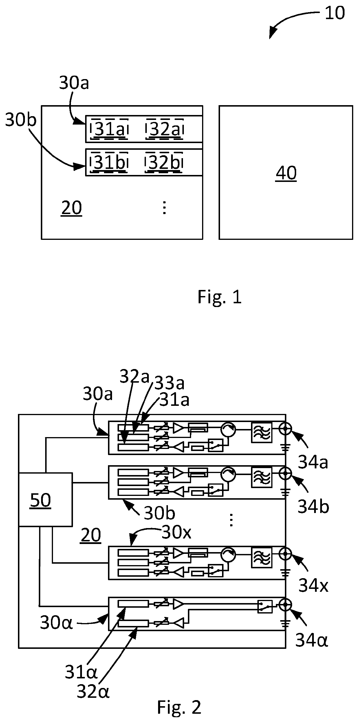
[0030]FIG. 1 depicts schematically an embodiment of an active antenna system 10, AAS 10. The AAS 10 comprises an antenna array 40. An embodiment of an antenna array is depicted in FIG. 4a-b and will be described in more detail later on. The AAS 10 comprises a radio unit 20. The radio unit 20 comprises a plurality of transceiver branches 30a, 30b, . . . Each of the transceiver branches 30a, 30b, . . . can comprise a corresponding transmitter 31a, 31b, . . . Each of the transceiver branches 30a, 30b, . . . can comprise a correspond...


PUM


Abstract

A method for calibrating an active antenna system (AAS). The AAS comprises a radio unit and an antenna array. The radio unit comprises a plurality of transceiver branches. The method comprises calibrating at least one, but less then all, out of the plurality of transceiver branches as reference branch or branches. The method further comprises calibrating non-calibrated transceiver branch or branches out of the plurality of transceiver branches while the antenna array and the radio unit are connected. The disclosure further relates to a method for onsite automatic maintenance of an active antenna system, and to an active antenna system.

Description

CROSS-REFERENCE TO RELATED APPLICATIONS[0001]This application is a National stage of International Application No. PCT / SE2018 / 050356, filed Apr. 5, 2018, which is hereby incorporated by reference.TECHNICAL FIELD[0002]The present disclosure relates to a method for calibrating an active antenna system, to a method for onsite automatic maintenance of an active antenna system, and to an active antenna system.BACKGROUND ART[0003]Base stations can comprise several transceiver branches. There are, for example, traditional base stations comprising two or four transceiver branches on the market. These base stations are usually calibrated and tested in a factory in connection to their production. Usually, each transceiver branch is calibrated and tested in the factory prior delivery of the base station to a customer. The testing and calibrating can be performed by connecting a factory test bench to the respective transceiver branch.[0004]Modern base stations, such as base stations comprising ...

Claims


Application Information

Patent Timeline
Patent Type & Authority Patents(United States)
IPC IPC(8): H04B17/12H04B17/14H01Q1/24H01Q21/00
CPCH04B17/12H01Q1/246H01Q21/00H04B17/14H04B17/18H04B17/19H04B17/21
Inventor LIAO, JICHANGSU, YOUPING
Owner TELEFON AB LM ERICSSON (PUBL)
Why Eureka
Try Eureka