Method and apparatus for modulating light

a light modulator and light technology, applied in the field of light modulators, can solve the problems of many electrophoretic modulators, limited or no ability to modulate certain wavelengths of light, and low electrical power consumption of optical displays, so as to reduce or eliminate at least.

Active Publication Date: 2013-02-19
RAYTHEON CO
View PDF1 Cites 0 Cited by
  • Summary
  • Abstract
  • Description
  • Claims
  • Application Information

AI Technical Summary

Benefits of technology

[0005]The present disclosure provides a method and apparatus for modulating light. Particular embodiments substantially reduce or eliminate at least some of the disadvantages and problems associated with previous light modulators.
[0008]Important technical advantages of certain embodiments of the present invention include a modulator capable of providing high optical reflectance in one state and high optical absorption in another state. Additionally, particular embodiments may capable of modulating incident light incident such that light across one or more specific spectral bands is reflected, scattered, absorbed, or otherwise modulated with an electronically-controlled average intensity. Furthermore, particular embodiments of the modulator may support rates greater than or equal to video rates (>30 Hz), have appropriate spectral bandwidth, provide high optical (on / off) contrast, and operate at very low electrical power.

Problems solved by technology

This can result in optical displays with very low electrical power consumption.
Despite their benefits, many electrophoretic modulators suffer from (1) limited or no ability to modulate certain wavelengths of light with high contrast, and (2) limited or no ability to reflect light in a specular manner.
The use of electrophoretic particles can make it easy to obtain high optical absorption, but difficult to obtain high specular reflectance due to the random, diffuse nature of light scattering from an ensemble of small particles.

Method used


Image

  • Method and apparatus for modulating light
  • Method and apparatus for modulating light
  • Method and apparatus for modulating light

Examples


Embodiment Construction

[0005]The present disclosure provides a method and apparatus for modulating light. Particular embodiments substantially reduce or eliminate at least some of the disadvantages and problems associated with previous light modulators.

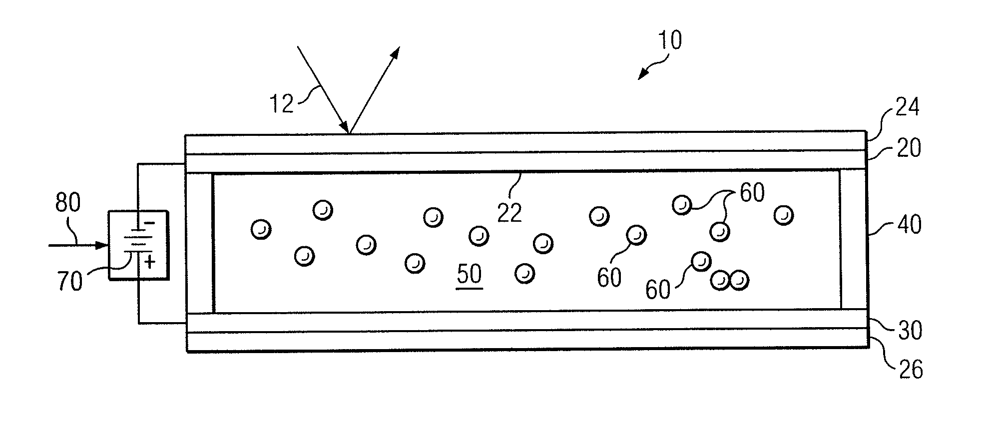
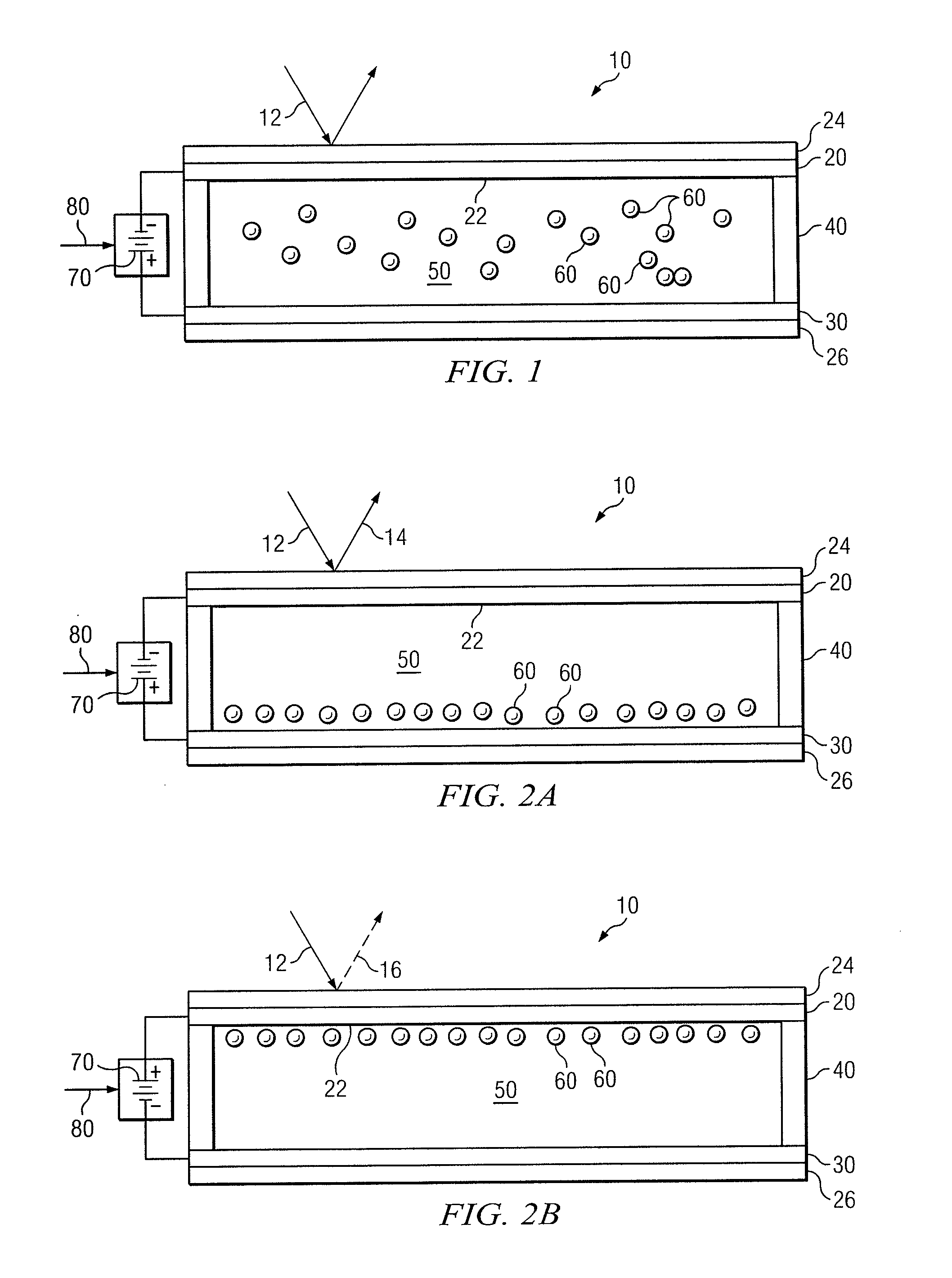
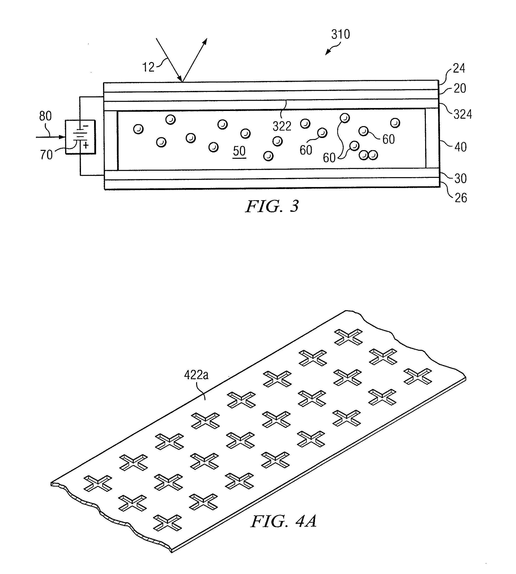
[0006]In accordance with one embodiment described by the present disclosure, an apparatus for modulating light includes a first electrode, a second electrode, and a sealed enclosure. The first electrode includes a frequency selective surface operable to reflect light having a first wavelength, and the second electrode is spaced apart from the first electrode. The sealed enclosure stores electrophoretic fluid and at least a portion of the sealed enclosure is positioned between the first electrode and the second electrode. A plurality of particles are suspended in the electrophoretic fluid. The particles are capable of absorbing light having the first wavelength. In addition, the first electrode is capable of attracting the particles towards the frequency sel...


PUM

PropertyMeasurementUnit
dielectric constantaaaaaaaaaa
design wavelengthaaaaaaaaaa
first wavelengthaaaaaaaaaa

Abstract

An apparatus for modulating light includes a first electrode, a second electrode, and a sealed enclosure. The first electrode includes a frequency selective surface operable to reflect light having a first wavelength, and the second electrode is spaced apart from the first electrode. The sealed enclosure stores electrophoretic fluid and at least a portion of the sealed enclosure is positioned between the first electrode and the second electrode. A plurality of particles are suspended in the electrophoretic fluid. The particles are capable of absorbing light having the first wavelength. In addition, the first electrode is capable of attracting the particles towards the frequency selective surface when an electrical bias is applied between the first electrode and the second electrode.

Description

TECHNICAL FIELD[0001]This disclosure relates generally to light modulators and, in particular, to light modulators that utilize electrophoretic particles.BACKGROUND OF THE INVENTION[0002]Electrophoretic light modulators utilize electric fields to control the movement of electrically-charged particles that are typically suspended in fluid. In a typical, electrophoretic light modulator an electric force provided by a battery is used to cause such particles to move toward or away from a viewing surface. The electrodes in such a modulator may be made optically transparent and arranged as a parallel plate capacitor with the electrophoretic particles filling the void between the plates. In such a configuration, particles of differing color may be alternatively moved to or away from the viewing surface so that the color of certain portions of the surface change based on the color of the affected particles.[0003]Unlike the structurally-similar liquid crystal light modulators, electrophoreti...

Claims


Application Information

Patent Timeline
Patent Type & Authority Patents(United States)
IPC IPC(8): G02B26/00G02F1/167G02F1/1676
CPCG02F1/167G02F1/195G02F2001/1676G02F1/1676
Inventor FRAZIER, GARY A.
Owner RAYTHEON CO
Why Eureka
Try Eureka