Loudspeaker based on the " center of percussion" or the " sweet spot" point, with gas filled hollow oscillating member and fluid flooded voice coil
What is AI technical title?
AI technical title is built by Patsnap AI team. It summarizes the technical point description of the patent document.
a loudspeaker and center of percussion technology, applied in the field of loudspeakers, can solve the problems of soft dome loudspeakers, piston-like motion, limitations of this concept, etc., and achieve the effects of improving sound dumping, improving sound quality, and improving sound dumping
Inactive Publication Date: 2005-01-20
ILIES ANDREI N
View PDF0 Cites 2 Cited by
Summary
Abstract
Description
Claims
Application Information
AI Technical Summary
This helps you quickly interpret patents by identifying the three key elements:
Problems solved by technology
Method used
Benefits of technology
Benefits of technology
[0009] The sound is created as effect of a wiping action of the oscillating member on the mass of air in the proximity of its surface. By allowing for a combination of piston like motion of portions of the oscillating member and predominant transversal oscillation to occur and by being able to acoustically insulate the front from the backside, the proposed loudspeaker in the preferred embodiment will have a high efficiency. To attain an also high level of sound reproduction quality, in the preferred embodiment of the present invention, the oscillating member of the loudspeaker is attached to its surrounding frame in a minimum number of joints of pivoting or unidirectional flexing type, set in case of the pivoting elements in pairs along the width of the frame and in case of the flexing elements, along the width of the frame, on one or both ends of the oscillating member.
[0010] These joints allow only one degree of freedom of motion and in case of the pivoting type absorb the least amount of energy, allowing for the greatest freedom of movement.
[0013] In a second alternative to the preferred embodiment of the invention, furthermore the two sides apart from the center of mass of the entire oscillating member can be considered as moving their centers of masses in a translation and only their parts aside from their centers of mass towards the ends of the entire oscillating member will rotate around the respective centers of mass of the very parts of the oscillating member. This development will bring about two additional points where the inertial forces show balance in a particular case, that is, no reactions in the center of mass of the two parts of the entire oscillating member on each side of the center of mass of the entire oscillating member. These two points, if used as locations for pivoting points, would bring about an outstanding dynamic stability for the entire oscillating member, translated in acoustic terms, the highest quality of sound attainable from the system. The voice coil in this case is placed the best in the center of mass of the entire oscillating member.
[0015] Another alternative to the preferred embodiment of the invention is to create a cavity or cavities inside the oscillating member to enable a closer control of density and distribution of mass. Also, the replacement of the air inside the cavity or cavities with a suitable gas, will improve the sound dumping inside the oscillating member by changing the sound speed inside the cavities with immediate effect on sound pitch, and consequently directivity and reflection, A rubber bladder is installed in the proximity of the oscillating member, connected to the cavities, to compensate for the variation in volume of the gas due to temperature changes.
[0016] In a last alternative to the preferred embodiment of the invention, the loudspeaker is held in a horizontal position with the gap of the permanent magnetic assembly surrounding the voice coil facing upwards. In this position, and having the central part of the permanent magnetic assembly provided with an opening that communicates from the front side of the oscillating member with the cavity of the permanent magnetic assembly, a heat exchanging fluid can be introduced around the voice coil. This will enable the loudspeaker to handlehigher power loads as well as improve the dumping of free oscillations where necessary.
[0017] The result is an unprecedented quality of sound and efficiency, compact and economical to manufacture loudspeaker, as presented in the preferred embodiment of the invention and further accompanied by drawings that illustrate the principles of the invention.
Problems solved by technology
The main disadvantage of the cone type loudspeakers, including the hard and soft dome loudspeakers, is the fact that they act in a piston like motion.
These two facts, when analyzed from the energetic point of view, will bring about the limitations of this concept.
Also part of the acoustic energy in front of the oscillating membrane will be cancelled in the very instant of sound creation due to the acoustic transparency of the membrane, which will not be able to block in a satisfactory way the acoustic waves in opposition of phase generated on the rear side of the membrane.
The disadvantage of a generally stiff and thick membrane is that it is not able to allow the propagation of transversal waves in two different directions, perpendicular in general, without the introduction of unwanted stresses in the material it is made of.
Certain designs of planar loudspeakers have adopted an elongated shape of the membrane and the advantages are noticeable, but the unnecessary internal stressing of their poorly balanced membrane will still bring about a high level of distortion.
Method used
Image
Click on the blue label to locate the original text in one second.
Reading with bidirectional positioning of images and text.
Examples
Embodiment Construction
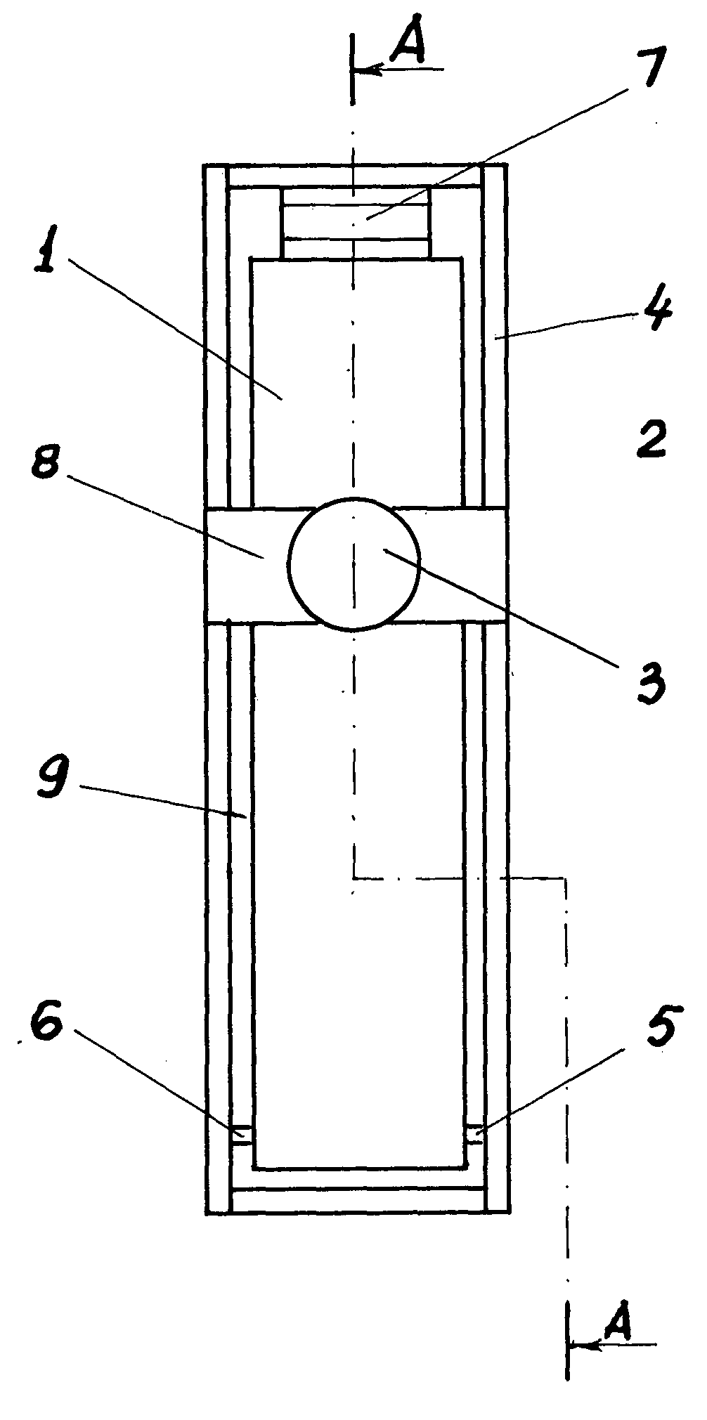
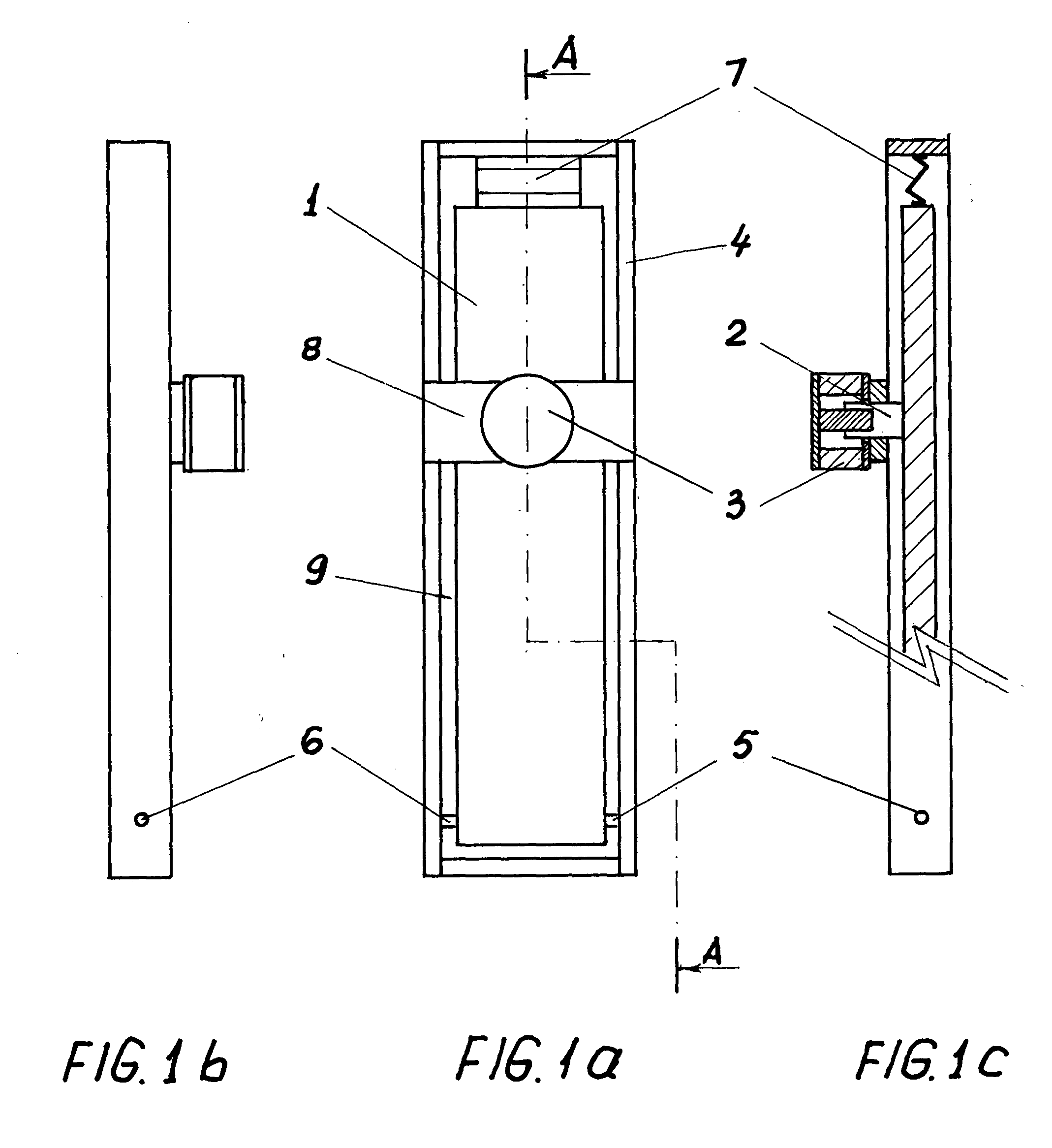
[0039]FIG. 1a is showing the loudspeaker as the oscillating member (I) surrounded by the solid frame (4). The permanent magnet assembly (3) is mounted on the bridge (8). The pair of pivoting points (5) and (6) is holding the first end of the oscillating member (1). The flexible element (7) is holding the second end of the oscillating member (1) and attaches to the frame (4). An air gap (9) is present between the frame (4) and the oscillating member (1). The position of the voice coil is centered over the width of the oscillating member and is in the area of the center of percussion of the entire oscillating member about the axis of the points (5) and (6) in one alternative to the preferred embodiment of the invention. The vibrations induced by the voice coil in the oscillating member will not be transferred into the pair of pivots (5)-(6) according to the principle of “The Center of Percussion”. It looks as if the vibration is not affected by the presence of this pair of pivots, whi...
PUM
Abstract
A loudspeaker, having a not necessarily rectangular, planar or constant thickness oscillating member, made of relatively thick, low density, stiff, acoustic insulating material, in an elongated form, surrounded by a solid frame, supporting the oscillating member in a minimum number of pivots or flexible elements, placed in areas of points of specific dynamic balance, like one end, center of mass and center of percussion about a certain axis of the oscillating member. The oscillating member is set in vibration by a permanent magnet driver having the voice coil attached to the oscillating member and the permanent magnetassembly supported by a bridge mounted across the frame. In an alternative preferred embodiment the oscillating member is built to incorporate at least one cavity filled with air or a gas different from air. In an alternative preferred embodiment the horizontally placed oscillating member has at least one voice coil immersed in a heat transferring fluid introduced in the cavity of the electromagnetic driver.
Description
REFERENCES CITED [REFERENCED BY][0001] U.S. Patent Documents [0002] U.S. Pat. No. 4,003,449 January, 1977 Bertani 181 / 173. U.S. Pat. No. 4,184,563 January, 1980 Bertani 181 / 171. U.S. Pat. No. 4,257,325 March, 1981 Bertani 181 / 172. U.S. Pat. No. 4,997,058 March, 1991 Bertani 181 / 166. U.S. Pat. No. 5,007,707 April, 1991 Bertani 359 / 444. U.S. Pat. No. 5,425,107 June, 1995 Bertani 381 / 426. U.S. Pat. No. 5,693,91 December, 1997 Bertani 181 / 173. U.S. Pat. No. 5,615,275 March, 1997 Bertani 381 / 431. U.S. Pat. No. 6,058,196 May, 2000 Heron 381 / 152. U.S. Pat. No. 6,160,898 December, 2000 Bachmann 381 / 425. U.S. Pat. No. 6,278,90 Aug., Davis 381 / 398.BACKGROUND OF THE INVENTION [0003] This invention relates to loudspeakers, but is not limited to the subject. [0004] The dynamic loudspeakers having an electromagnetic driver coil attached to a membrane, which is brought to oscillation are mainly of two categories, the cone type, including the dome type loudspeakers and the planar type loudspeakers....
Claims
Application Information
Patent Timeline
Application Date:The date an application was filed.
Publication Date:The date a patent or application was officially published.
First Publication Date:The earliest publication date of a patent with the same application number.
Issue Date:Publication date of the patent grant document.
PCT Entry Date:The Entry date of PCT National Phase.
Estimated Expiry Date:The statutory expiry date of a patent right according to the Patent Law, and it is the longest term of protection that the patent right can achieve without the termination of the patent right due to other reasons(Term extension factor has been taken into account ).
Invalid Date:Actual expiry date is based on effective date or publication date of legal transaction data of invalid patent.
Patent Type & AuthorityApplications(United States)

