

Chill blocks and methods for manufacturing chill blocks
- Summary
- Abstract
- Description
- Claims
- Application Information
AI Technical Summary
Benefits of technology
Problems solved by technology
Method used
Image

Examples
second embodiment
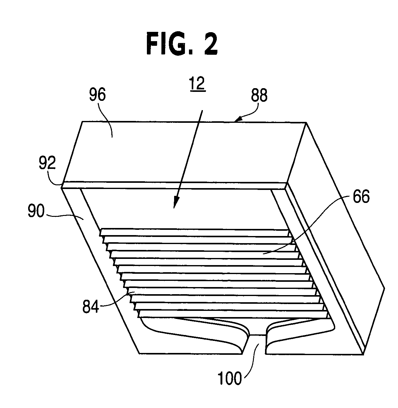
[0033] In the present invention, the chill block base 88 is made from a material, for example, copper or a metallic mixture including copper, for example, beryllium copper. A layer having a thickness, of less than about 0.5 inches and preferably ranging from about 0.060 to about 0.090 inches, of a tool steel is applied, for example, by a spraying technique, such as the rapid solidification process developed at the Idaho National Engineering and Environmental Laboratory, to the parting line surface / chill face 90 of the chill block base 88 and around a portion 92, 94 of the sides 96, 98 of the chill block 12. In addition, a layer of tool steel is present on the bottom of the chill block base 88.
third embodiment
[0034] In the present invention, a layer of tool steel is not present on any portion of the sides 96, 98 of the chill block 12.
[0035]FIG. 3 is a flow chart illustrating a preferred embodiment of a new method 102 for manufacturing a chill block. The process of manufacturing a chill block in accordance with the preferred embodiment of the present invention involves applying a layer of a first material, for example tool steel, having a thickness of less than about 0.5 inches and preferably ranging from about 0.060 to about 0.090 inches, on an inside surface of a mold that is a negative of the chill block being formed 104.
[0036] Preferably, a rapid solidification process is utilized to apply the tool steel. A second material, for example, copper or beryllium copper is added on top of the first material, preferably, by the rapid solidification process 106. The tool steel is porous. When the copper metal is added on top of the tool steel, the copper metal fills the pores formed in the to...
PUM
| Property | Measurement | Unit |
|---|---|---|
| Thickness | aaaaa | aaaaa |
| Flow rate | aaaaa | aaaaa |
| Shape | aaaaa | aaaaa |
Abstract
Description
Claims
Application Information