

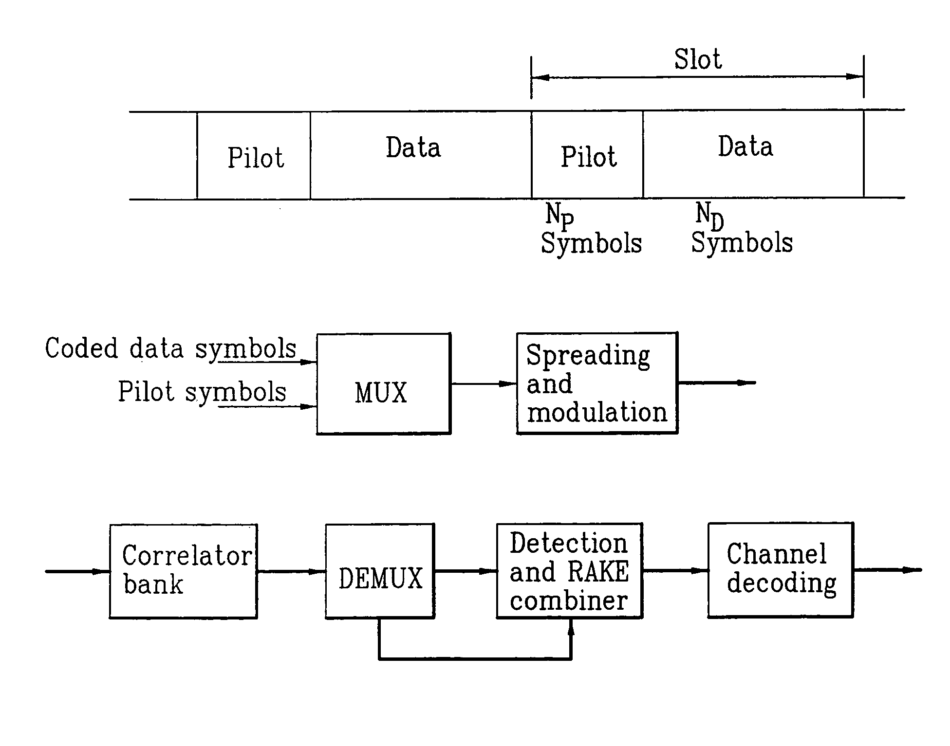
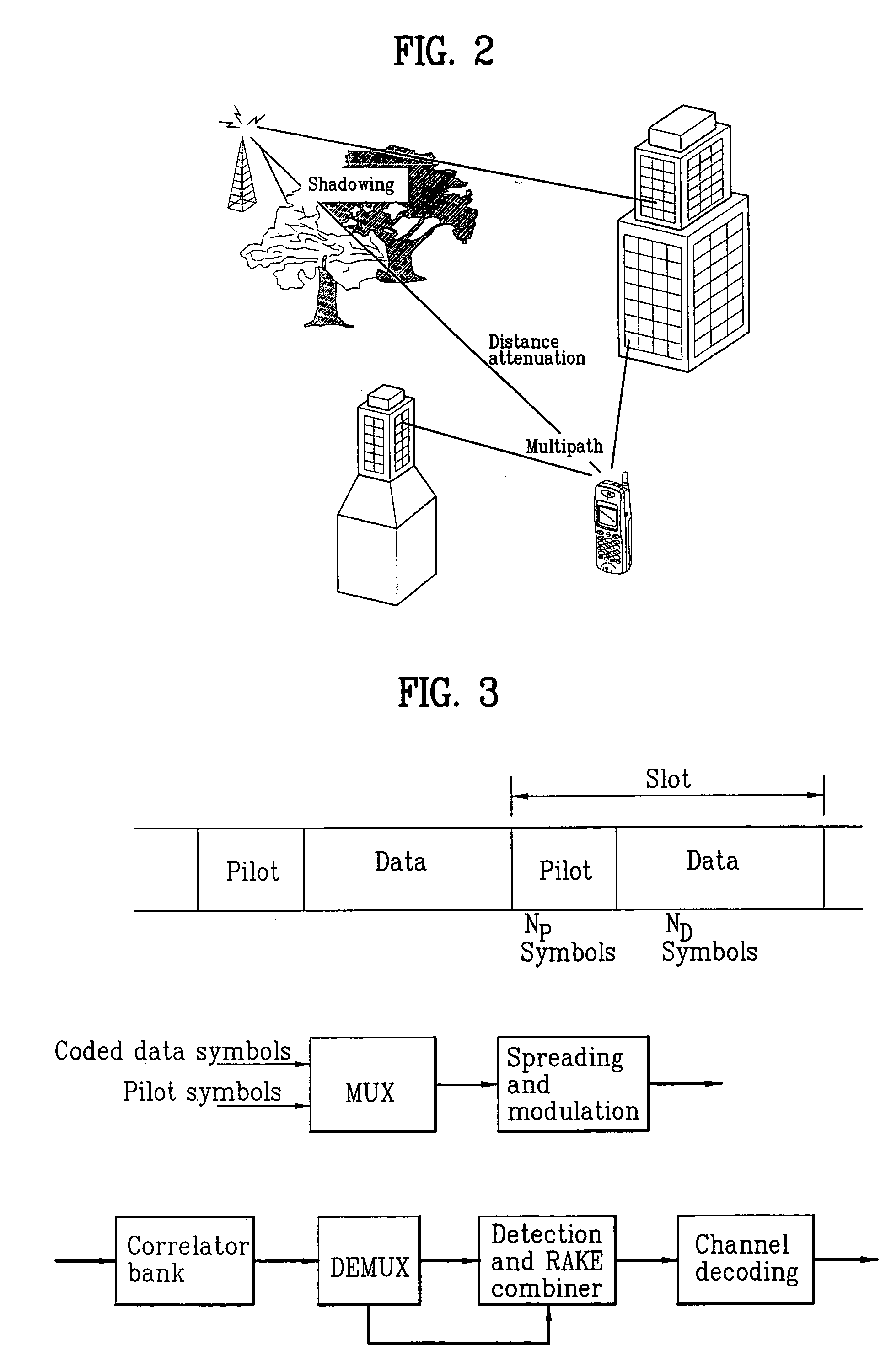
Pilot signals for synchronization and/or channel estimation
a pilot signal and channel estimation technology, applied in the field of communication systems, can solve the problems of difficult to achieve channel estimation for coherent detection, received signal suffers from frequency selective multipath fading, and is difficult to predict its behavior, so as to eliminate or prevent sidelobes, the effect of optimal autocorrelation results
- Summary
- Abstract
- Description
- Claims
- Application Information
AI Technical Summary
Benefits of technology
Problems solved by technology
Method used
Image

Examples
first embodiment
of Downlink DPCH, PCCPCH and SCCPH for STTD Diversity
FIG. 19A illustrates new pilot symbol patterns of Downlink DPCH for the diversity antenna using a space time block coding based transmit diversity (STTD). For the diversity pilot symbol pattern on downlink DPCH, STTD is applied to the shaded pilot symbols #1 and #3 for Npilot=8, and the shaded pilot symbols #1, #3, #5, and #7 for Npilot=16. The non-shaded pilot symbols #0 and #2 for Npilot=8, and non-shaded pilot symbols #0, #2, #4, and #6 for Npilot=16 are encoded to be orthogonal to the pilot symbol of FIG. 15A. However, the diversity pilot pattern for downlink DPCH with Npilot=4 are STTD encoded since STTD encoding requires two symbols. FIG. 19B illustrates the mapping relationship between the 8 words C1-C8 of FIG. 12A and shaded pilot symbol patterns of FIG. 19A.
FIG. 19C illustrates the new diversity antenna pilot symbol pattern for PCCPCH. The pilot symbols of FIG. 19C are encoded to be orthogonal to the pilot symbols of FIG...
PUM
 Abstract
Description
Claims
Application Information