Massage machine

a massage machine and foot technology, applied in the field of massage units, can solve the problems of inability to uniformly massage the soles or to give massage to a position, the foot is difficult to place into or out of the recessed receiving portion, and the person is likely to feel discomfor

Inactive Publication Date: 2005-02-10
SANYO ELECTRIC CO LTD
View PDF2 Cites 41 Cited by
  • Summary
  • Abstract
  • Description
  • Claims
  • Application Information

AI Technical Summary

Benefits of technology

[0012] The massage unit thus constructed is adapted to massage the affected part with varying intensities, enabling the user to feel as if being manually given a natural massage.

Problems solved by technology

Thus, the pressure members are reciprocatingly movable forward and backward on the same line and are therefore unable to uniformly massage the entire soles or to give massage to a position laterally away from the line of the movement of the members.
Accordingly, if the line of the movement differs from the desired position, for example, due to a difference in the size of the foot of the person to be treated, the person is likely to feel discomfort.
Furthermore, the foot is very difficult to place into or bring out of the recessed receiving portion because the foot holding cover becomes an obstacle, while it is likely that the foot holding cover feels tight.

Method used


Image

  • Massage machine
  • Massage machine
  • Massage machine

Examples


first embodiment

[0028] [First Embodiment]

[0029] The first embodiment is a foot massage unit 4 to which the invention is applied.

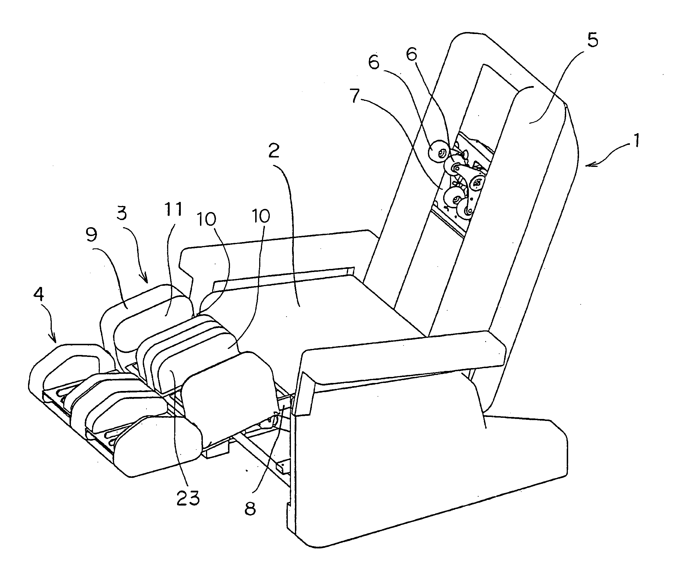
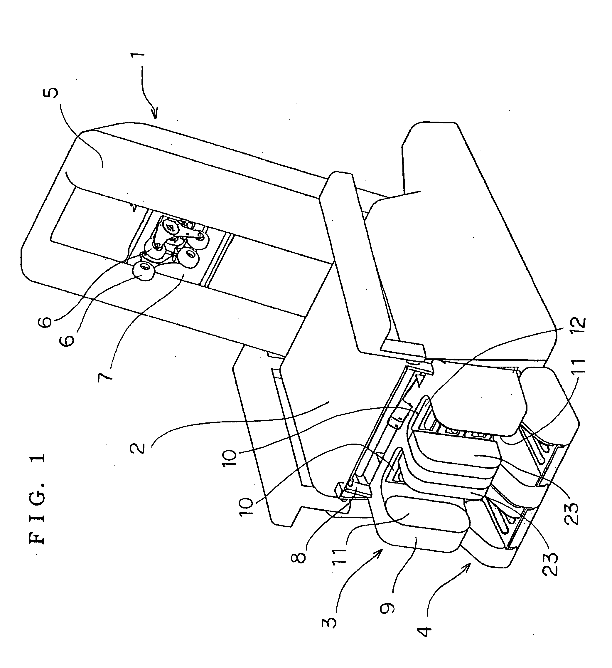
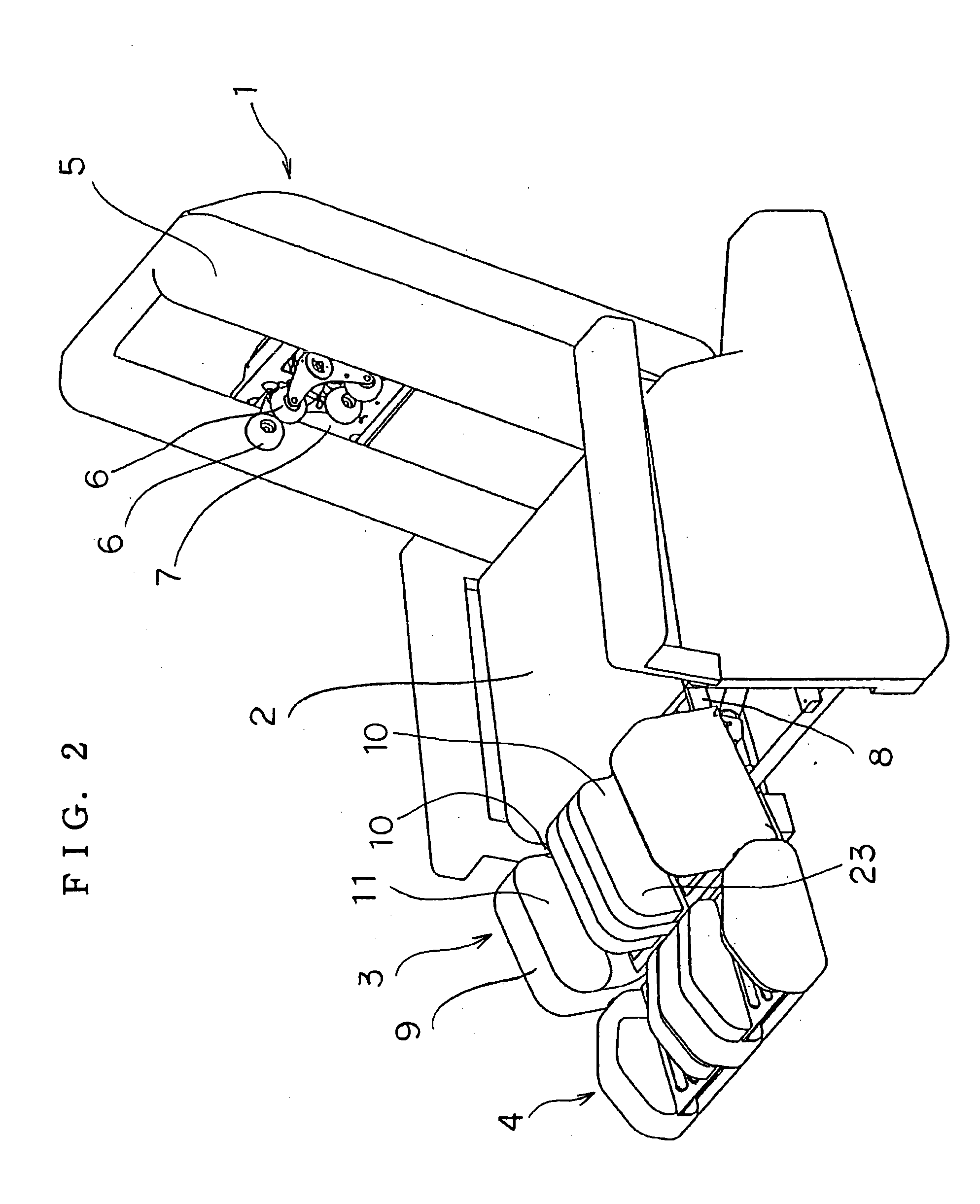
[0030] The foot massage unit 4 can be installed in a massage machine 1 of the chair type. With reference to FIG. 1, the massage machine 1 comprises a leg massage unit 3 positioned in front of a seat 2, and a foot massage unit 4 below the leg massage unit 3. The chair-type massage machine 1, as well as the leg massage unit 3, can be of known construction.

[0031] For example, the massage machine 1 comprises a massage mechanism 7 having a pair of left and right therapeutic members 6, 6 on a backrest 5 as shown in FIGS. 1 and 2. The massage mechanism 7 is movable upward and downward along the backrest 5 and is adapted to give a kneading massage to the person to be treated by moving the therapeutic members 6, 6 toward or away from each other, and to give a tapping massage by pivotally moving the therapeutic members 6, 6 upward and downward. The backrest 5 is covered with a fab...

second embodiment

[0046] [Second Embodiment]

[0047] The second embodiment has pressure member drive means 16 which is different from that of the first embodiment. Throughout the drawings concerned, like parts are designated by like reference numerals and will not be described repeatedly. A motor 33 mounted on a frame 27 centrally thereof serves as a drive source for the pressure member drive means 16. The motor 33 has an output shaft 34 which is coupled to a pulley 36 by a belt 35. A shaft 37 is provided on the pulley 36 by a press fit centrally thereof. The shaft 37 is rotated with the pulley 36 by the rotation of the motor 33. The shaft 37 has its opposite ends rotatably supported by a generally U-shaped support members 38 on the frame 27. As shown in FIG. 10, a generally cylindrical cam 39 is eccentrically fixed to the shaft 37 at the portion thereof positioned inside the support member 38. A pressure member 40 movable upward and downward is provided between the cam 39 and the support member 38.

[0...

third embodiment

[0050] [Third Embodiment]

[0051] FIGS. 11 to 13 show a third embodiment of the invention, wherein side air bags 15, 15a are provided on the respective opposite side walls of the recessed receiving portion 14. Throughout the drawings concerned, like parts are designated by like reference numerals and will not be described repeatedly.

[0052] With reference to FIG. 11, side air bags 15, 15a are provided respectively on opposite side walls of each recessed receiving portion 14. This arrangement makes it possible to adjust the position of the foot F relative to the pressure members 24, 24 with greater ease.

[0053] For example, if the opposed side air bags 15, 15a are inflated equally as seen in FIG. 11, the foot F is positioned approximately in the center of the recessed receiving portion 14, consequently enabling the pressure members 24 to massage the sole emphatically approximately at the center thereof.

[0054] Further if only the side air bag 15a positioned closer to the center of the ...


PUM


Abstract

An object of the invention is to provide a massage unit wherein means for massaging the affected part of the person to be treated is provided with means for moving the affected part so as to give massage to a desired position.
The massage unit of the invention comprises a recessed receiving portion 14 having a bottom wall 18 and opposite side walls 20, 21 extending upward from respective opposite sides of the bottom wall 18 for accommodating the affected part of the user therein, position adjusting means 15, 15a provided on the inner surfaces of the respective side walls 20, 21 of the recessed receiving portion 14 and movable toward the other side wall, and massage means 24 disposed on the bottom wall 18 of the recessed receiving portion 14 for massaging the affected part.

Description

TECHNICAL FIELD [0001] The present invention relates to massage units having recessed receiving portions which are adapted to give massage at the bottoms thereof to the feet or like affected parts as placed therein. BACKGROUND ART [0002] Foot massage units are available which are adapted to massage the soles or like affected parts of the person to be treated and which comprise recessed receiving portions for placing the feet thereinto, and a foot holding cover for covering the insteps. The person to be treated inserts his or her feet into the respective receiving portions to have the insteps pressed by the holding cover, and is given massage on the soles by pressure members projecting upward from behind the soles (see the publication of JP-A No. 2000-167021). [0003] With the massage unit described, the pressure members serving as massage means are movable usually only forwardly and backwardly of the recessed receiving portions but are not movable leftward or rightward. Thus, the pre...

Claims


Application Information

Patent Timeline
Patent Type & Authority Applications(United States)
IPC IPC(8): A61H1/00A61H39/04A61H7/00A61H15/00A61H23/04A61H37/00
CPCA61H2201/0149A61H2201/1669A61H2205/081A61H2205/12A61H2015/0028A61H15/0078A61H23/04A61H39/04A61H7/001A61H23/006A61H2201/0103A61H2201/1409A61H2205/106
Inventor NAKAMURA, TAKASHIKOMA, TOSHIKISUZUKI, TAKAMASA
Owner SANYO ELECTRIC CO LTD
Why Eureka
Try Eureka