Massage device

a technology of massage device and foot, which is applied in the field of massage device, can solve the problems of uneven stimulation of the uneven stimulation of the bottom of the toes and foot arch of the entire sole of the foot, and the constant position of the foot on the massage device, so as to achieve effective foot massage, increase the load, and improve the effect of massage

Inactive Publication Date: 2008-05-01
MARUTAKATECHNO
View PDF4 Cites 6 Cited by
  • Summary
  • Abstract
  • Description
  • Claims
  • Application Information

AI Technical Summary

Benefits of technology

[0009] The present invention provides a massage device including a pair of therapeutic elements (or massaging elements) and a bottom therapeutic member. The therapeutic elements are rotated by a driving shaft, driven by a driving mechanism, to support and massage feet. The bottom therapeutic member is disposed between two therapeutic elements, for supporting an instep of a foot. The therapeutic elements are formed along an instep of a foot. Since the therapeutic elements are formed along the instep, the load is increased, and stimulation on the sole of the foot can be intensified, further preventing the foot from upward movement resulting in the foot slipping off the device. Thus, the present invention provides effective foot massage.
[0010] The present invention further has a protrusion disposed on a side of the therapeutic elements, facing the instep of a foot, abutted from above by the protrusion for massaging. Since the protrusion faces the instep of a foot on the therapeutic elements, the protrusion presses the instep from above. When the foot is massaged from above by the protrusion, the foot is prevented from slipping upward and off the device, while maintaining optimal foot position, effectively stimulating the foot.
[0011] At least two of the therapeutic elements are disposed along the longitudinal direction of the foot. Thus, the present invention can effectively massage the foot, according to shape.
[0012] The protrusion is an airbag. Accordingly, the protrusion corresponds to the foot in both shape and size, uniformly applying pressure over the entire foot. The airbag can be expanded, thus, decreasing the distance between two therapeutic elements, thereby restricting the foot, and providing an adequate massaging pressure. Furthermore, when the pressure of the airbag is greater than a certain value, the mechanical valve discharges excess compressed air for safety, thus, controlling stimulation and increasing durability.

Problems solved by technology

As a result, if the shape of the outer periphery of the uniquely shaped members conforms to the shape of a user's ankle and foot arch, the massage device unevenly stimulates the bottom of toes and foot arch of the entire sole of the foot when placed thereon.
Thus, maintaining the position of a foot on the massage device and applying weight thereon provides uneven stimulation.

Method used


Image

  • Massage device
  • Massage device
  • Massage device

Examples


first embodiment

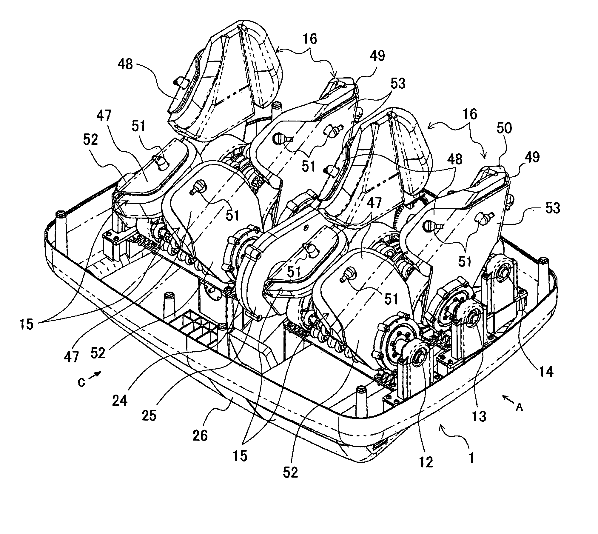
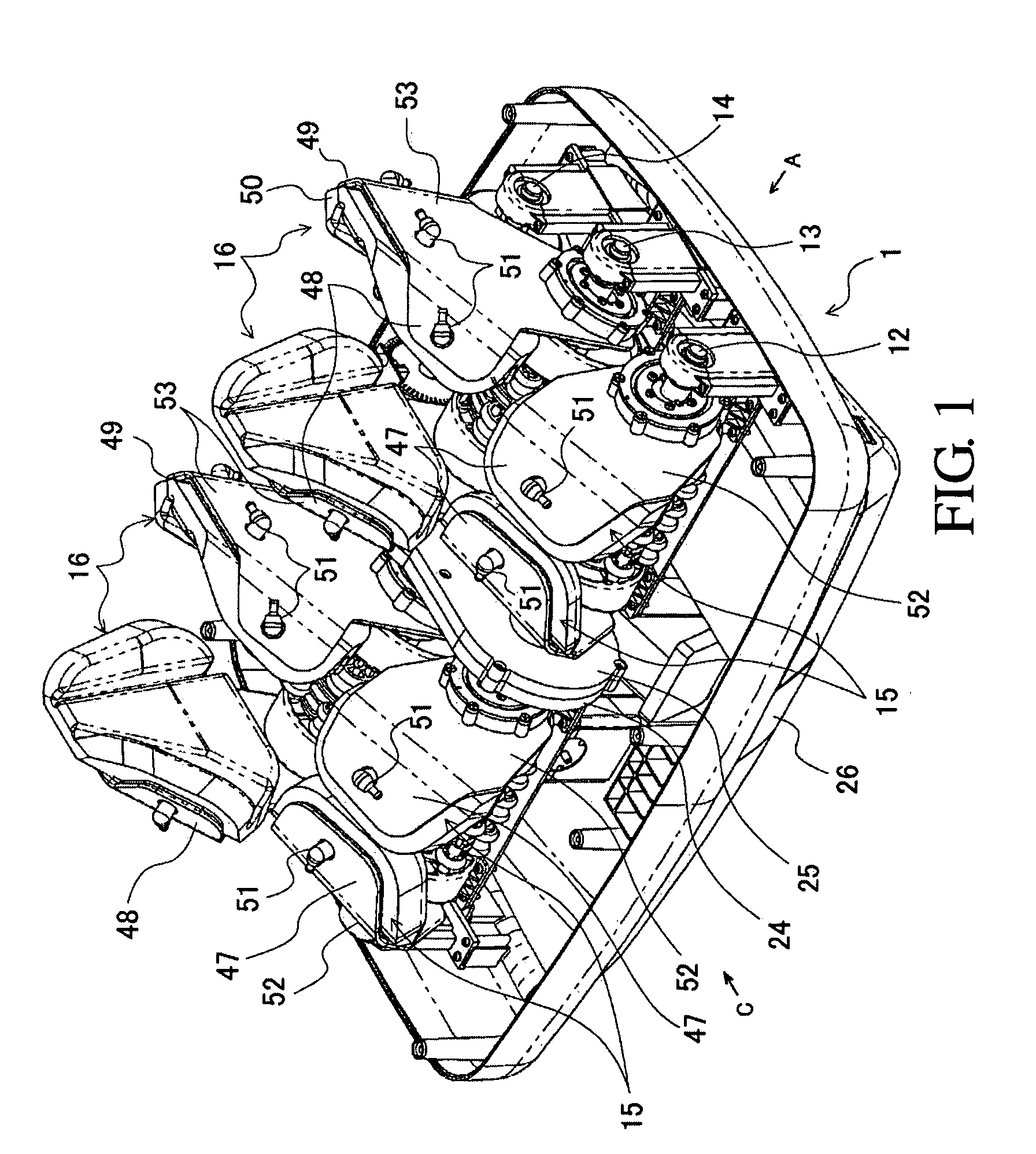
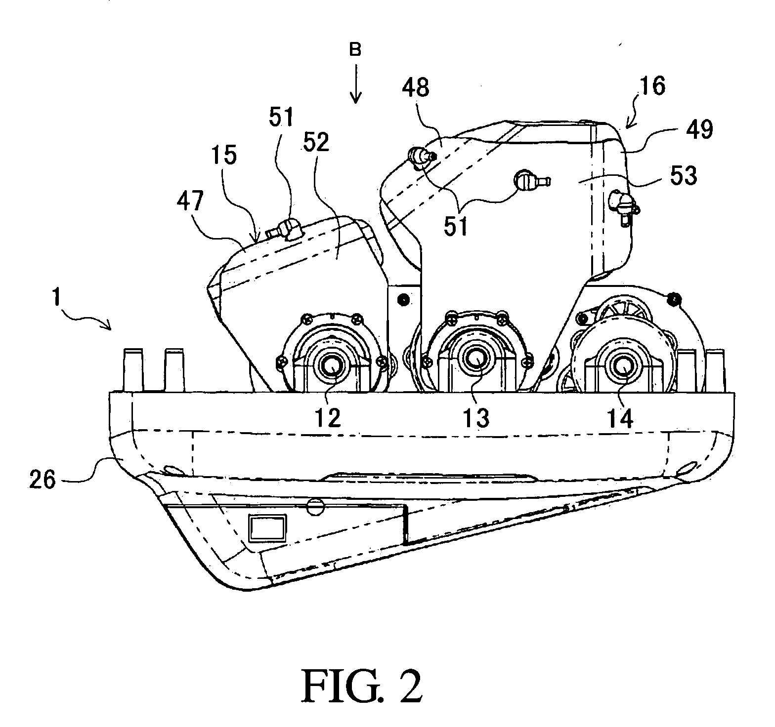
[0036]FIGS. 1-10 are schematic views according to the present invention. Symbol 1 of FIG. 1 represents the massage device. In the massage device 1, rotational driving force of a motor 18 is transmitted to a rotational shaft 19 of worm and helical gears 20, 21, 22 of a driving mechanism 17 to drive driving shafts 12, 13, 14. Rollers 9, 10, and 11 of bottom therapeutic members are disposed on the driving shafts 12, 13, 14, respectively. The rollers 9, 10, and 11 are driven by the driving shafts 12, 13, 14 in a predetermined direction. The bottom of a patient's forefoot, not shown in the figure, can be placed on the roller 9. The roller 10 is disposed at a position corresponding to an arch of a foot of a patient. The roller 11 is disposed at a position corresponding to the heel of the patient. Therapeutic protrusions 6, 7, and 8 are provided on the rollers 9, 10, and 11, for generating higher pressure than the pressure provided by the weight of a patient's foot.

[0037] A pair of therape...

second embodiment

[0050]FIGS. 11 and 12 are schematic views according to the present invention. Symbols 80 and 81 in FIGS. 11 and 12 are substitutes for therapeutic elements 15 and 16. The therapeutic elements 80 and 81 include massaging bases 45 and 46, massaging plates 82, and pressing blocks 84 and 85. The flat massaging bases 45 and 46 are fixed symmetrically on left and right sides, and rotated axially with respect to the driving shafts 12 and 13. On the outer periphery of each massaging base 45 and 46, a massaging plate 82 is fixed axially by a bearing 54 and inserted at an angle with respect to the driving shafts 12 and 13. Each pressing block 84 or 85 is disposed on an opposite side of the top end of each massaging plate 82. Each pressing block 84, 85 and the massaging plate 82 form an L-shaped cross section for massaging the instep of the forefoot. The guiding portion 49 having adequate flexibility, as shown in FIGS. 1 and 3, is formed according to the shape of a foot. As a result, by provid...

third embodiment

[0051]FIGS. 13 and 14 are schematic views according to the present invention. Symbols 90 and 91 in FIGS. 13 and 14 are substitutes for therapeutic elements 15 and 16. The therapeutic elements 80 and 81 include massaging bases 45 and 46, massaging plates 82, and pressing blocks 92. The flat massaging bases 45 and 46 are fixed symmetrically on left and right sides, and rotated axially with respect to the driving shafts 12 and 13. On the outer periphery of each massaging bases 45 and 46, a massaging plate 82 is fixed axially by a bearing 54 and inserted at an angle with respect to the driving shafts 12 and 13. Each pressing block 92 is disposed on an opposite side of the top end of each massaging plate 82. Each pressing block 92 and the massaging plate 82 form an L-shaped cross section for massaging the instep of the forefoot. The guiding portion 49 having adequate flexibility, as shown in FIGS. 1 and 3, is formed according to the shape of the foot. As a result, by securely pressing th...


PUM


Abstract

A massage device. The massage device includes a pair of therapeutic elements and a bottom therapeutic member. The therapeutic elements are rotated by a driving shaft, driven by a driving mechanism, for supporting and massaging feet. The bottom therapeutic member is disposed between two therapeutic elements, supporting the instep of a foot. The therapeutic elements are formed along the instep.

Description

CROSS REFERENCE TO RELATED APPILCATIONS [0001] This application is a Divisional of pending U.S. patent application Ser. No. 10 / 748,324, filed Dec. 30, 2003 and entitled “MASSAGE DEVICE,” incorporated herein by reference.BACKGROUND OF THE INVENTION [0002] 1. Field of the Invention [0003] The present invention relates to a massage device, and in particular to a massage device for massaging and stimulating the sole of the foot. [0004] 2. Description of the Related Art [0005] In a conventional massage device disclosed by Japan patent No. 2001-224648, in order to provide foot massage and stimulation, an outer periphery thereof is protruded at an acute angle. A plurality of therapeutic rollers with circular, rigid arc-shaped elements having a radius of curvature of 10 mm to 15 mm are supported by rotating shafts. A locus of rotary motion of the rotating shafts is determined by uniquely shaped members. Each rotating shaft has a row of the therapeutic rollers provided thereon. A row of ther...

Claims


Application Information

Patent Timeline
Patent Type & Authority Applications(United States)
IPC IPC(8): A61H7/00A61H15/00A61H39/04
CPCA61H15/0078A61H2205/12A61H2015/0035E04D3/352E04D3/363
Inventor ISHIGURO, FUMITAKAISHIKAWA, TETSUYA
Owner MARUTAKATECHNO
Why Eureka
Try Eureka