Remotely accessible power controller for building lighting

a power controller and remote access technology, applied in the direction of electric controllers, ignition automatic control, instruments, etc., can solve the problems of inconformity, retrofit modification of existing building lighting control systems with additional control wiring, and inability to automatically shut off the light, so as to improve the reliability of power line carrier communications, prevent interference from external noise sources, and reduce the effect of electrical nois

Inactive Publication Date: 2005-01-11
SIGNIFY NORTH AMERICA CORP
View PDF12 Cites 144 Cited by
  • Summary
  • Abstract
  • Description
  • Claims
  • Application Information

AI Technical Summary

Benefits of technology

Interference from external noise sources is prevented by using an in-line high frequency blocking filter and a command signal transmitter for each communication channel. The high frequency blocking function is realized by a low pass filter circuit characterized by a relatively low attenuation signal transfer function from DC through the power distribution frequency up to a cut-off frequency below the power line carrier modulation frequency, and characterized by a relatively high attenuation signal transfer function that suppresses or substantially attenuates all other signals above the cut-off frequency. This filter function essentially allows the PLC power controller to dominate the lighting branch circuits by blocking the transmission of all noise sources and unwanted foreign command signals originating externally to the PLC network, and blocking the reverse transmission of high frequency noise originating internally from active branch loads and local command signals applied to the branch conductors. The power controller generally improves the reliability of power line carrier communications in an end user alternating current power distribution network, for example, in a commercial building power distribution network having existing power distribution conductors that service multiple, diverse loads such as halogen incandescent lamps with a switched step-down power supply, standard incandescent lamps with a high frequency dimmer and fluorescent lamps with an electronic ballast dimmer.
Each communication channel is isolated from external noise and spurious signal sources by an in-line high frequency blocking filter in combination with a command signal transmitter that boosts the signal strength, for example to 7.0 V peak-to-peak, not only when the network signals cross phases but also between each branch circuit on the network. At least 500 mV or higher signal strength is recommended even though signal routing (firewall protection) requires only 35 mV or less signal strength for reliable operation. The higher level is recommended to accommodate any other equipment or power surges that might weaken the signal. This coupled with the in-line high frequency blocking filter on each channel virtually eliminates any interference from spurious signal sources and electrical noise and compensates for additional loading caused by noise generated on other lines that degrade the signal strength, for example from computers, laser printers, surge-protection devices, induction motors and the like.

Problems solved by technology

The majority of existing commercial buildings are not equipped for automatic light shut off operation, and thus are not presently in compliance with ASHRAE / IESNA Standard 90.1.
The retrofit modification of existing building lighting control systems with additional control wiring incurs considerable costs and provides only limited flexibility in configuring an existing lighting control network to accommodate automatic time-of-day disconnect schedules.
Many lighting installations are not equipped for dimming, so that a curtailment request when implemented means that the work force must be sent home.
The majority of existing commercial buildings are not equipped for automatic light shutoff or dimming operation, so that considerable retrofit wiring is required.
Consequently, even for small installations, a large amount of wiring is necessary to connect all of the lights with their respective power dimmers, and to connect the power dimmers to their respective controllers.
Because of the phase difference, it is difficult to utilize conventional light dimming systems that employ a microprocessor controlled memory unit for selectively controlling the application of power to a specific group of lighting loads, individual ones of which may be separately energized by phase A, phase B power and phase C power.
There are substantial high frequency noise and interfering signals such as harmonics of the power signal, switching transients, etc. that interfere with the PLC command signals.
A major limitation on the use of power line carrier communications is spurious signals and background noise including impulse noise.
Such noise can originate from the power source, the distribution network, loads coupled to the distribution network and from remote sources.
Additionally noise may be introduced from the loads (including switching transients).
This introduces harmonics and high frequency noise on the power distribution conductors.
This high frequency noise makes it more difficult to communicate reliably over power lines particularly since some of the harmonics and noise associated with the power distribution fall within the frequency range of the PLC command signals.
Each of a variety of load devices can conduct a significant level of noise back onto the power line.
Different loads and control devices produce different types and degrees of noise that may interfere with the flow of information over the power line.
Another potential limitation on PLC signaling is signal attenuation.
This significant attenuation in combination with noise interference makes reliable PLC communication very difficult.
Moreover, even the mode of operation of particular load devices on the power line network may differentially affect the noise or attenuation levels throughout the network.
The reliability of such systems is compromised when the signal-to-noise ratio is low.
In particular, this increases system vulnerability to spurious signals and sensitivity to electrical noise, causing lost messages, false interpretation and spurious activation.
These types of noise disturbances can occur any time during the day, night or on a weekly basis, causing erratic communication including false turn-ON / turn-OFF of PLC—controlled devices.
Low signal strength means erratic or loss of control on the most distant devices from a PLC transmitting device.
Signal strength loss on a circuit can be due to several factors, including the number of interconnected PLC devices, power conductor losses and non-PLC devices on the circuit.
Wiring loss is due to the power wiring resistance and capacitance losses that reduce signal strength.
The greater the distance between a PLC device to another PLC device the more loss of signal strength occurs.
However, for each 50 feet length of 12 AWG Romex from one PLC device to another a loss of about 18% of the signal strength should be expected.
These couplers will further reduce the signal strength.
These do not solve the problem of other circuits that are on the same phase that might need to be amplified.
Since the distribution panel will normally be several feet from the PLC devices the wiring loses will further reduce the PLC signal strength.

Method used


Image

  • Remotely accessible power controller for building lighting
  • Remotely accessible power controller for building lighting
  • Remotely accessible power controller for building lighting

Examples


Embodiment Construction

A preferred embodiment of the invention will now be described with reference to various examples of how the invention can best be made and used. Like reference numerals are used throughout the description and several views of the drawing to indicate like or corresponding parts.

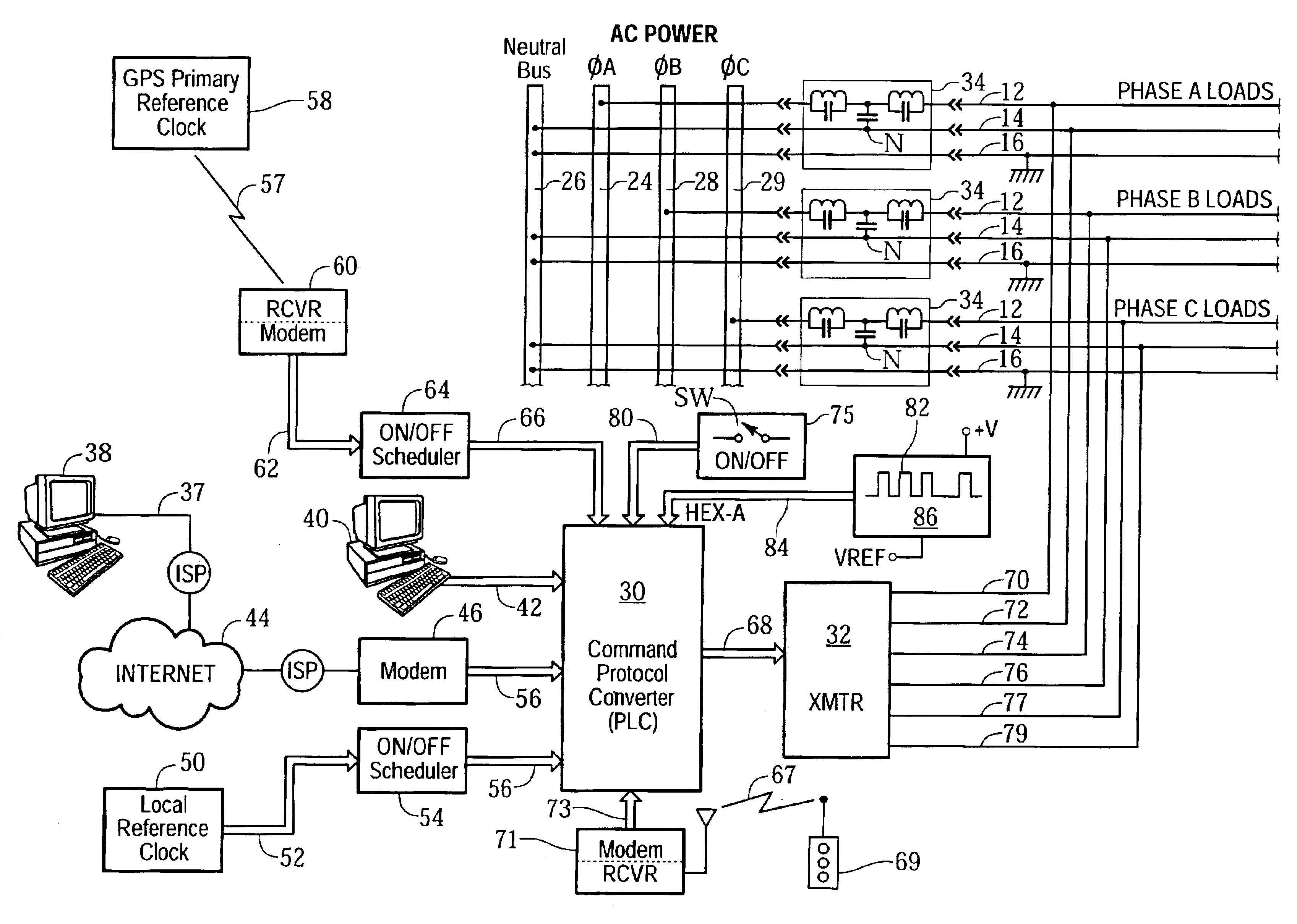
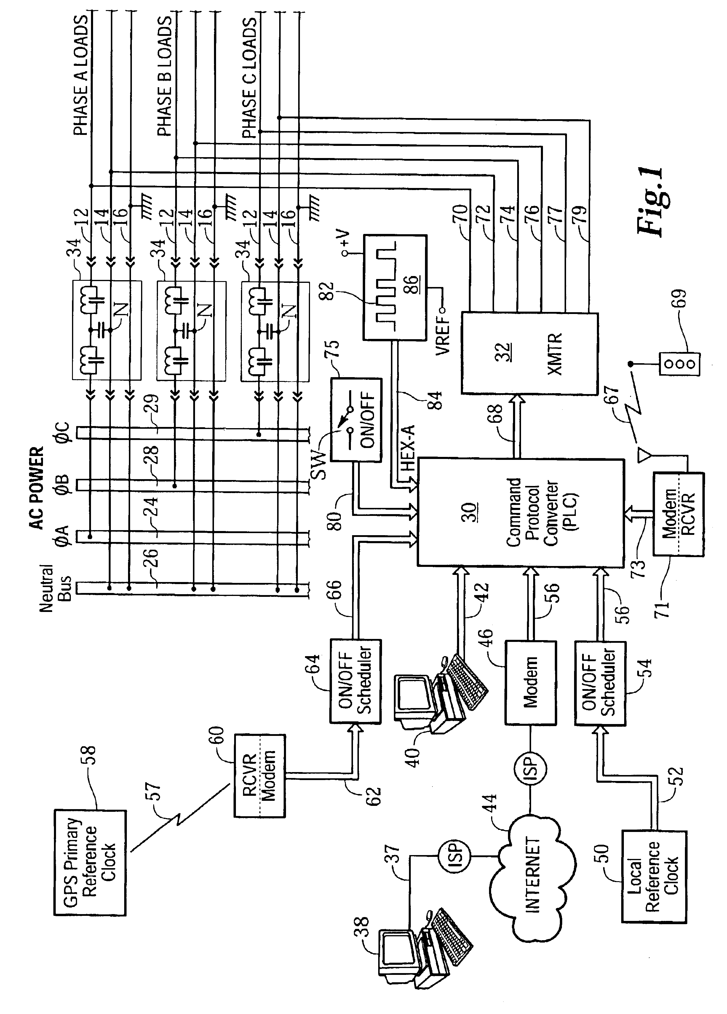
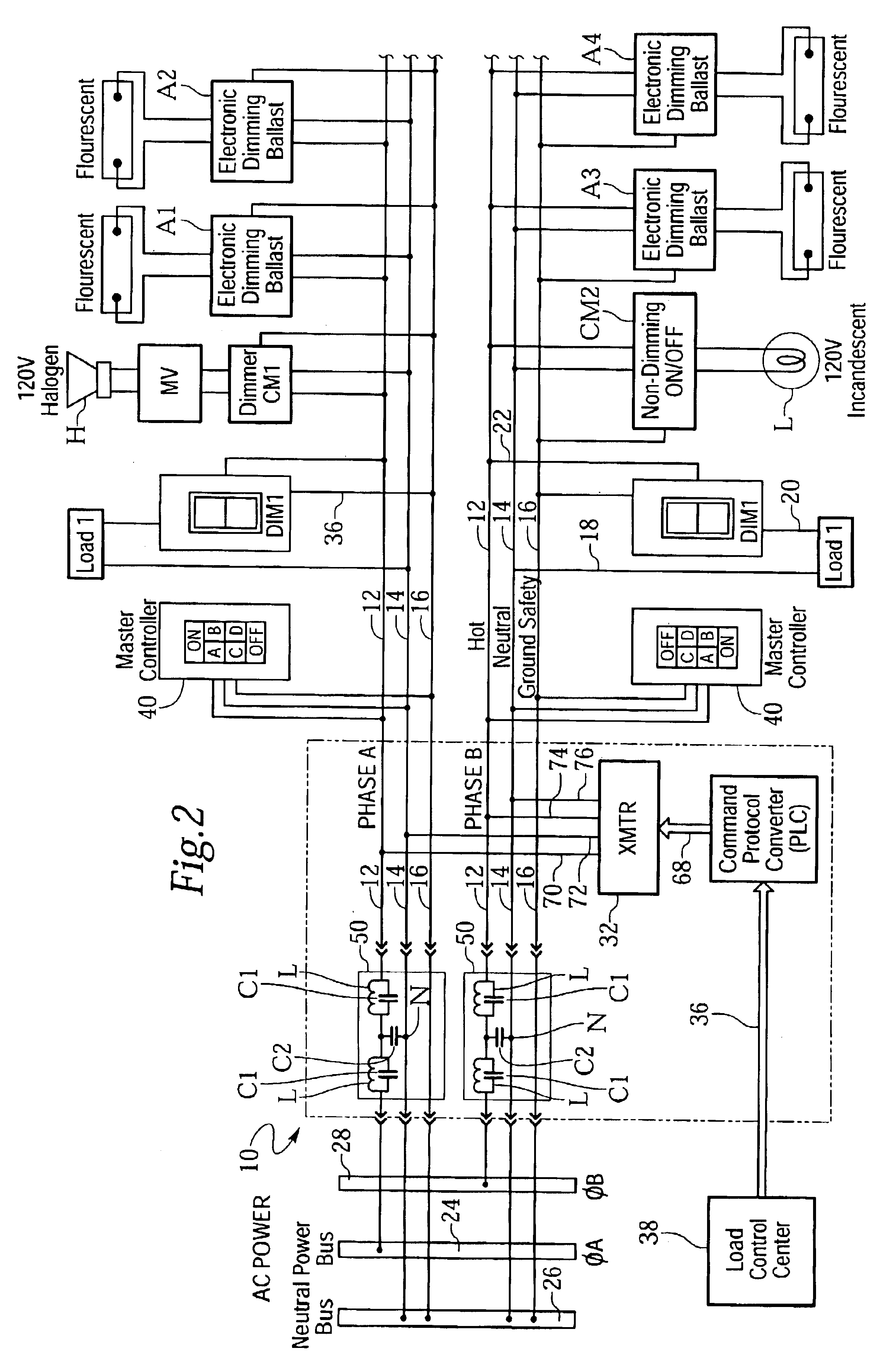
Referring now to FIG. 1 and FIG. 2, the power controller circuit 10 of the present invention will be described with reference to a typical AC power distribution system commonly used for 110 volts, 60 Hz AC power service, in which AC power is conducted via hot, neutral and ground safety power line conductors 12, 14 and 16, respectively in either three phases A, B and C (FIG. 1), or two phases A and B, (FIG. 2). The power lines of most electrical power distribution systems conduct alternating current (AC) at a selected operating voltage (e.g., 110 VAC, 120 VAC or 220 VAC) and power distribution frequency (usually 60 Hz in the U.S. and 50 Hz elsewhere) via one or more phases (e.g., single-phase, two-phase or thre...


PUM


Abstract

A remotely accessible power controller communicates power reduction command signals by power line carrier (PLC) signaling over existing AC power distribution conductors for automatically disconnecting building lighting loads. Turn-off command signals from a local or remote controller automatically disconnect building lighting loads according to a time-of-day schedule to comply with mandated energy consumption codes applicable to the automatic shutoff of electrical lighting. Load shedding (selective turn off and/or dimming) command signals transmitted from public or private utility companies automatically disconnect or reduce building lighting loads in accordance with load curtailment agreements to limit total connected power consumption below an agreed level. The power controller is connected by a minimum amount of retrofit wiring into an existing end-user alternating current power distribution network, for example, a building power distribution network having AC power conductors that service multiple lighting loads interconnected in one or more power phase groups. Each dimming lighting load is equipped with an addressable dimming module for decoding and executing dimming and turn-on and turn-off power reduction commands. Fluorescent lamps are equipped with addressable electronic dimming ballasts.

Description

BACKGROUND OF THE INVENTIONThis invention relates generally to electrical load controllers for saving energy in commercial buildings, and in particular to a remotely accessible power controller for automatically disconnecting building lighting loads to comply with energy consumption codes applicable to the automatic shutoff of electrical lighting, and for automatically disconnecting or dimming building lighting loads to limit total connected power consumption below an agreed level in accordance with load curtailment agreements with public or private utility companies.In an effort to make more efficient use of available energy resources, government authorities are adopting and mandating building energy codes. In particular, many jurisdictions have adopted the International Energy Conservation Code (IECC) which references ASHRAE / IESNA Standard 90.1 for commercial buildings. Part III (3) of that standard, concerning interior lighting, requires that all commercial buildings more than 50...

Claims


Application Information

Patent Timeline
Patent Type & Authority Patents(United States)
IPC IPC(8): H04B3/54H04B3/56
CPCH04B3/54H04B3/56H05B37/0263H04B2203/5483H05B47/185H02J2310/14H02J3/14
Inventor CARSON, STEVEN R.GRIFFIN, RAYMOND T.
Owner SIGNIFY NORTH AMERICA CORP
Why Eureka
Try Eureka