Disk augmentation system and method

a disk augmentation and disk technology, applied in the field of disk augmentation system and method, can solve the problems of reducing reducing reducing the ability of the relative motion between the two vertebrae, so as to facilitate the reduction of the load on one or more disks

Active Publication Date: 2007-10-16
X SPINE SYST
View PDF70 Cites 142 Cited by
  • Summary
  • Abstract
  • Description
  • Claims
  • Application Information

AI Technical Summary

Benefits of technology

[0007]It is, therefore, an object of the invention to provide a disk augmentation system for providing exterior support to one or more vertebrae and to facilitate reducing load on one or more disks.
[0009]In another aspect, this invention comprises an adjustable compression system for mounting to a plurality of vertebrae, a support for mounting on the vertebrae of a spinal column, and a retainer situated exterior of the spinal column for retaining a compression body outside a native disk space and an axis of the spine, the retainer facilitating reducing loading of at least one disk in the spinal column, the retainer comprising a first support for mounting to a first one of the vertebrae and a second support for mounting to a second one of the vertebrae, the first and second supports being adapted to permit the compression body to replicate or augment a function of a native or natural intervertebral disk by permitting the first support and the second support to become non-parallel relative to each other during use, and an adjustable tensioner for adjusting an amount of compression on the compression body between the first support and the second support after the first and second supports are mounted onto the first one of the vertebrae and the second one of the vertebrae, respectively, wherein the compression body is generally planar.
[0011]In yet another aspect, this invention comprises an adjustable compression system for reducing a load on at least one lumbar disk in a spinal column, the adjustable compression system comprising: a retainer for mounting on a first vertebra and a second vertebra of a spinal column, the retainer comprising a first artificial body support and a second artificial body support cooperating to define a retaining area for receiving an artificial body and for supporting the artificial body posterior of the first vertebra and the second vertebra, an adjuster adjusting an amount of loading on the artificial body after the first and second supports are mounted on the first and second ones, respectively, of the vertebrae; and the retainer cooperating with the artificial body to facilitate reducing load on the at least one lumbar disk when the first and second vertebrae move either toward or away from each other, and permitting the first artificial body support and the second artificial body support to become non-parallel relative to each other to replicate or augment a function of a native disk, the artificial body being generally planar.
[0014]In still another aspect, this invention comprises an adjustable compression system for reducing the load on at least one lumbar disk, the adjustable compression system comprising: a retainer for retaining a first compression body posterior of the spinal column and for facilitating reducing load on at least one lumbar disk in the spinal column, and a second retainer for mounting on the spinal column also for facilitating reducing load on the at least one lumbar disk, wherein the first and second retainers are not located along an axis of the spinal column.

Problems solved by technology

Because of the high forces on them, spinal disks commonly rupture, particularly as they deteriorate with age.
A difficulty with this is that relative motion between the two vertebrae is no longer possible, causing both stiffness in the spine and difficulties in areas above or below the fused disk.
A major problem with this approach is that it requires an extensive and technically demanding surgical procedure.
Such a procedure consists of surgical exposure through the abdomen of the patient, which risks injury to abdominal structures and usually requires the services of a multidisciplinary surgical team.
Meticulous and complete removal of the native disk is required prior to placement of such a device—a time consuming and technically difficult procedure.
These devices have the advantage of being relatively straightforward to place surgically through a rearward approach; however, they do not replicate the ideal biomechanical properties of a true prosthetic disk system.

Method used


Image

  • Disk augmentation system and method
  • Disk augmentation system and method
  • Disk augmentation system and method

Examples


Embodiment Construction

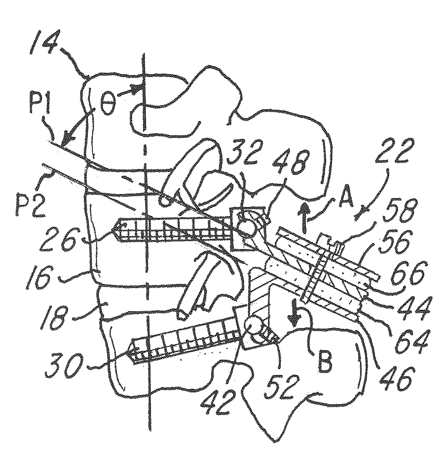
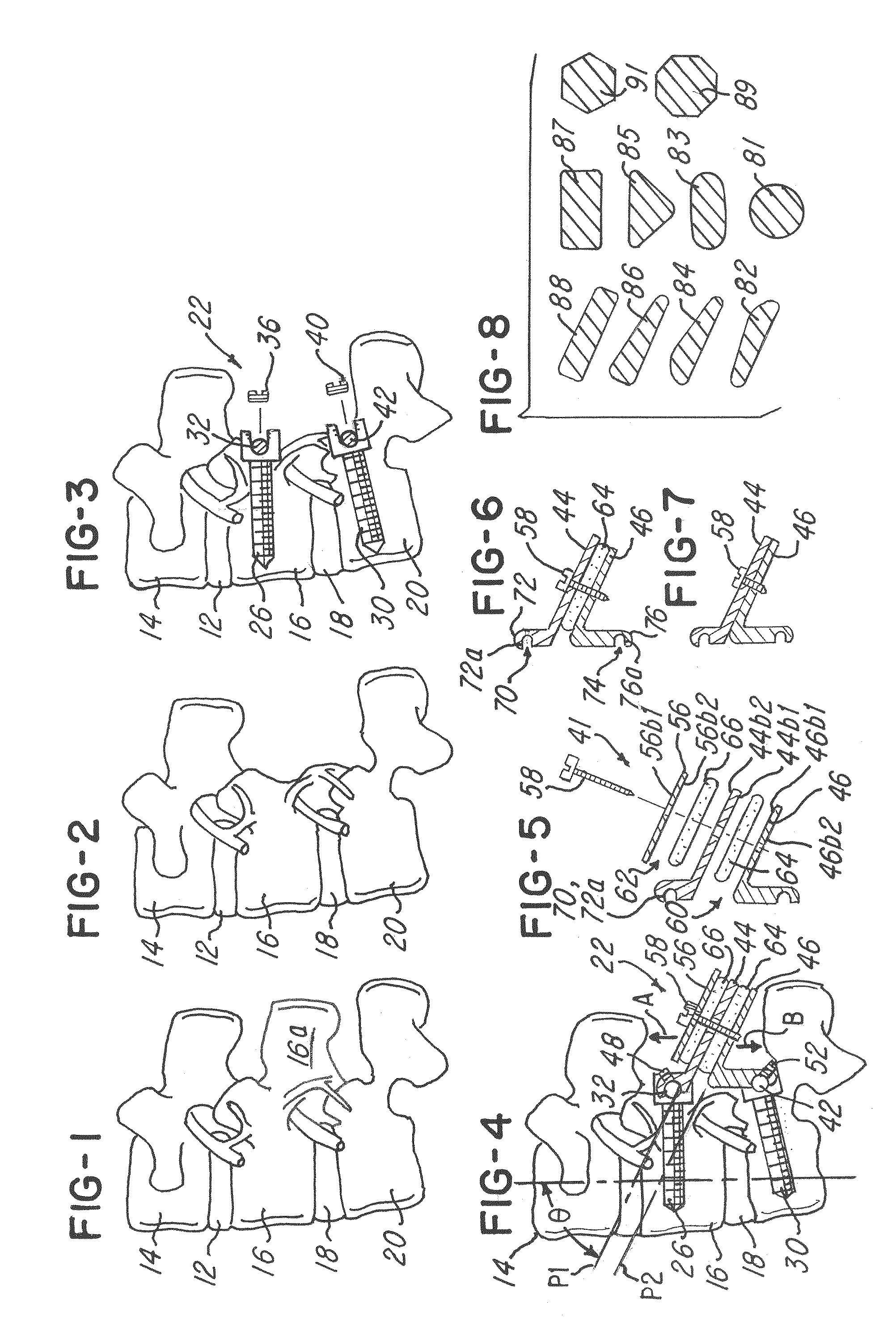
[0029]Referring now to FIGS. 1-11, a disk augmentation system and method will now be described. The system and method of the invention are used to facilitate reducing load on one or more disks, such as disk 12 between vertebrae 14 and 16 and disk 18 between vertebrae 16 and 20. The invention comprises means or a system 22 for reducing a load on at least one of lumbar disks when the vertebrae, such as vertebrae 14 and 16, move either away from or toward each other.

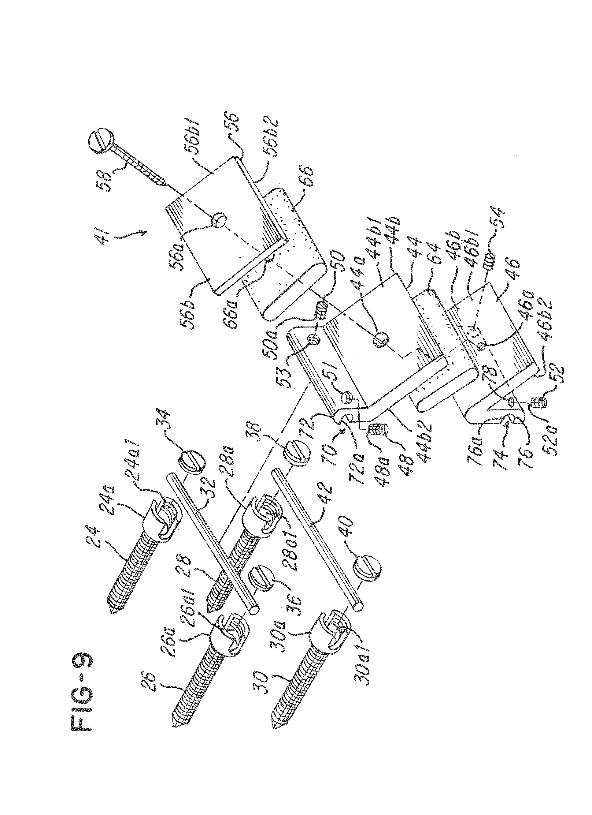
[0030]As illustrated in FIGS. 3, 4 and the exploded view in FIG. 9, the system 22 comprises a plurality of screws 24, 26, 28 and 30 comprising open heads 24a, 26a, 28a and 30a, respectively. In the embodiment being described, the open heads 24a, 26a, 28a and 30a comprise a receiving area 24a1, 26a1, 28a1 and 30a1, respectively. The areas 24a1, 26a1, 28a1 and 30a1 receive supports 32 and 42 as shown. For example, the open heads 24a and 26a receive a support or cylindrical rod 32 in the areas 24a1 and 26a1, respectively. The ...


PUM


Abstract

A disk augmentation system and method for situating a retainer comprising artificial supports posterior to or exterior of a spinal column and a spinal column axis. The system and method provides an external retainer having supports for receiving at least one artificial compression body and securing at least one artificial compression body in a supported relationship to facilitate reducing load on the one or more natural disks of a patient.

Description

BACKGROUND OF THE INVENTION[0001]This invention relates to a disk augmentation system and method for providing support for reducing load on one or more disks in a patient's spine.[0002]Human spines are formed from vertebrae, which are separated and cushioned from each other by disks. The disks consist of a fibrous outer envelope containing a gel-like fluid. The disks are subject to large forces, which may vary from about 175 pounds when a person is at rest to as high as about 500 pounds during activity. For example, a person who lifts a 15-pound weight one foot in front of such person, using a bending movement, can generate nearly 500 pounds of force on his or her spine. Because of the high forces on them, spinal disks commonly rupture, particularly as they deteriorate with age.[0003]Various attempts have been made to deal with the problem of a diseased intervertebral disk. One standard procedure is to remove the disk and fuse the vertebrae, which were formerly separated by the disk...

Claims


Application Information

Patent Timeline
Patent Type & Authority Patents(United States)
IPC IPC(8): A61F2/44A61B17/70A61F2/30
CPCA61B17/7031A61B17/7043A61F2002/30563A61F2/4405A61B17/7049
Inventor KIRSCHMAN, DAVID LOUIS
Owner X SPINE SYST
Why Eureka
Try Eureka