
Surface treating device with top load cartridge-based cleaning system

a technology of top-load cartridges and treating devices, which is applied in the direction of carpet cleaners, instruments, photosensitive materials, etc., to achieve the effects of preventing fluid delivery, easy loading of dust bins, and easy loading of fluid reservoirs

Active Publication Date: 2009-08-25
SC JOHNSON & SON INC
View PDF40 Cites 160 Cited by
  • Summary
  • Abstract
  • Description
  • Claims
  • Application Information

AI Technical Summary

Benefits of technology

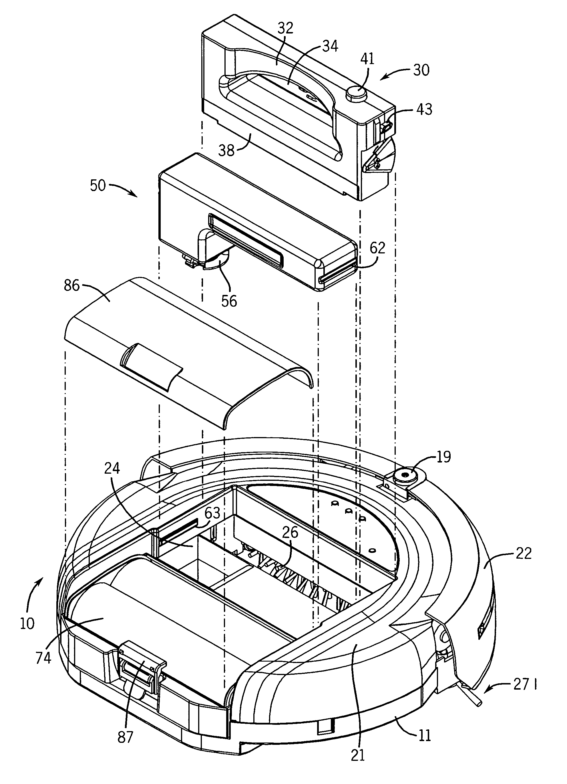
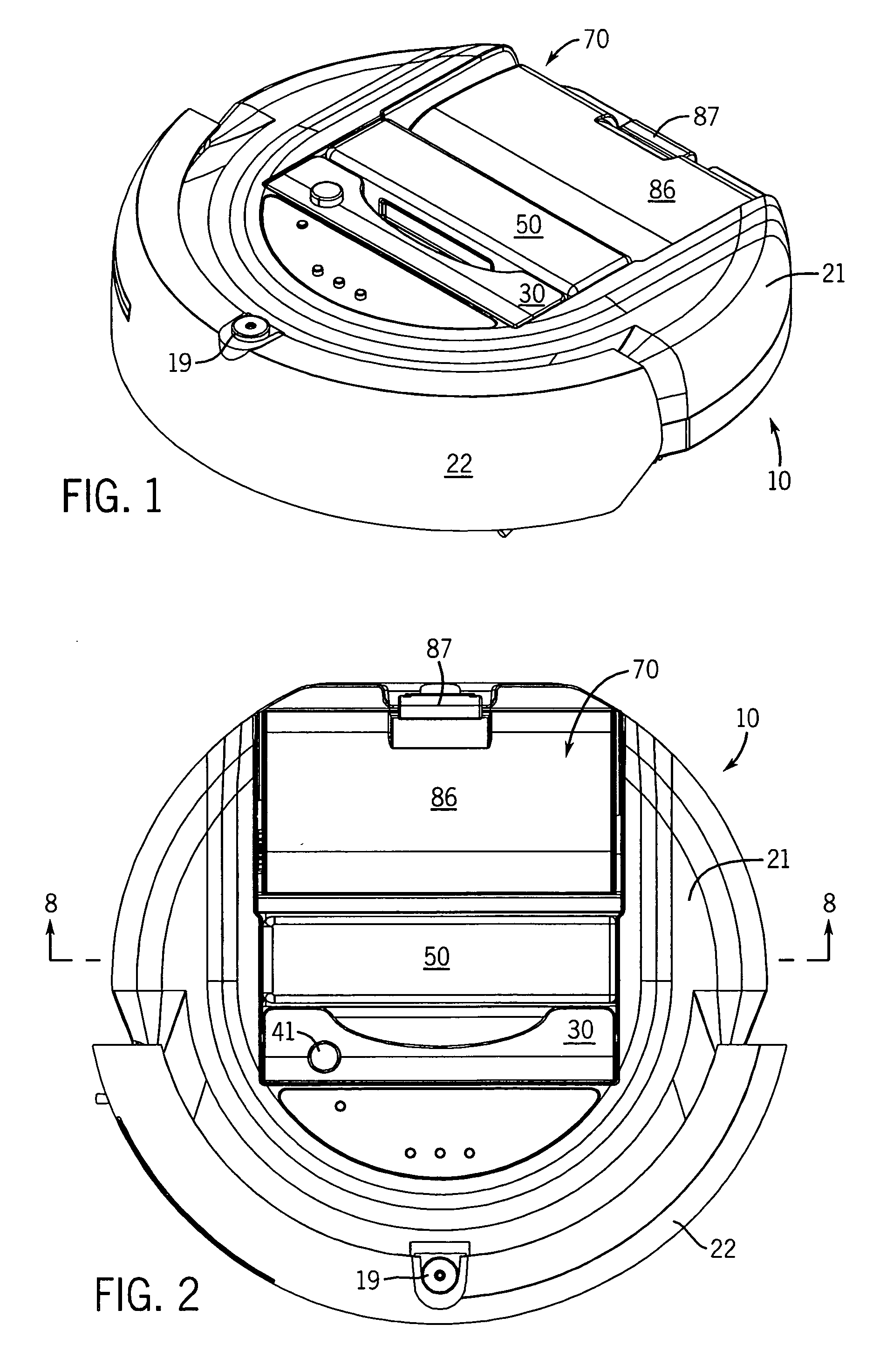
[0010]In one aspect, the invention provides a robotic surface treating device including a dust bin, a sheet of cleaning material, means for moving the sheet of cleaning material relative to a surface to be treated, and a housing including a compartment having an open end for separately removably receiving the dust bin and the sheet of cleaning material. In one configuration of the robotic surface treating device, the open end of the compartment faces upward when the device is placed on the surface to be treated. This allows a user to easily load the dust bin and the sheet of cleaning material in the top of the robotic surface treating device.
[0011]The robotic surface treating device may further include a fluid delivery system including a fluid reservoir. The open end of the compartment also separately removably receives the fluid reservoir. This allows a user to easily load the fluid reservoir in the top of the robotic surface treating device. The fluid delivery system may include a pump for delivering fluid from the fluid reservoir onto the sheet of cleaning material and / or the surface to be treated. The robotic surface treating device may include a wheel, means for measuring rotation of the wheel, and a controller in communication with the pump and the means for measuring rotation of the wheel. The controller provides fluid delivery signals to the pump such that fluid is not delivered onto the sheet of cleaning material and / or the surface to be treated when the rotation of the wheel is less than a predetermined amount. As a result, fluid delivery is prevented when the robotic surface treating device is stopped or moving slowly.
[0013]The means for moving the sheet of cleaning material may also include a cartridge for mounting the first roller and the second roller, and the open end of the compartment is dimensioned to separately removably receive the cartridge. The means for moving the sheet of cleaning material may also include a window for viewing the sheet of cleaning material in the cartridge. This allows a user to check to see when the sheet of cleaning material is used up and needs to be replaced. The means for moving the sheet of cleaning material may also include a platen for pressing the sheet of cleaning material against the surface being treated. This provides improved cleaning performance.
[0016]In another aspect, the invention provides a robotic surface treating device including a fluid delivery system including a fluid reservoir, a sheet of cleaning material, means for moving the sheet of cleaning material relative to a surface to be treated, and a housing including a compartment having an open end for separately removably receiving the sheet of cleaning material and the fluid reservoir. This aspect of the invention would be useful in environments where a dust bin and a sweeper brush are not desired. In one configuration of this version of the robotic surface treating device, the open end of the compartment faces upward when the device is placed on the surface to be treated. This allows a user to easily load the fluid reservoir and the sheet of cleaning material in the top of the robotic surface treating device.
[0018]As a result, fluid delivery is prevented when the robotic surface treating device is stopped or moving slowly.
[0020]In this aspect of the invention, the means for moving the sheet of cleaning material may also include a cartridge for mounting the first roller and the second roller, and the open end of the compartment is dimensioned to separately removably receive the cartridge. The means for moving the sheet of cleaning material may also include a window for viewing the sheet of cleaning material in the cartridge. This allows a user to check to see when the sheet of cleaning material is soiled and needs to be replaced. The means for moving the sheet of cleaning material may also include a platen for pressing the sheet of cleaning material against the surface being treated. This provides improved cleaning performance.

Problems solved by technology

What is lacking in the art is a robotic surface treating device where a dust bin, a fluid reservoir, and a reel-to-reel cartridge of cleaning material are each separately provided on the surface treating device, and once these devices are installed, they may be separately replaced when, for example, the dust bin is full, the fluid is used-up, or the cleaning cloth material is either used-up or soiled to the point of inefficiency.

Method used


Image

  • Surface treating device with top load cartridge-based cleaning system
  • Surface treating device with top load cartridge-based cleaning system
  • Surface treating device with top load cartridge-based cleaning system

Examples


Embodiment Construction

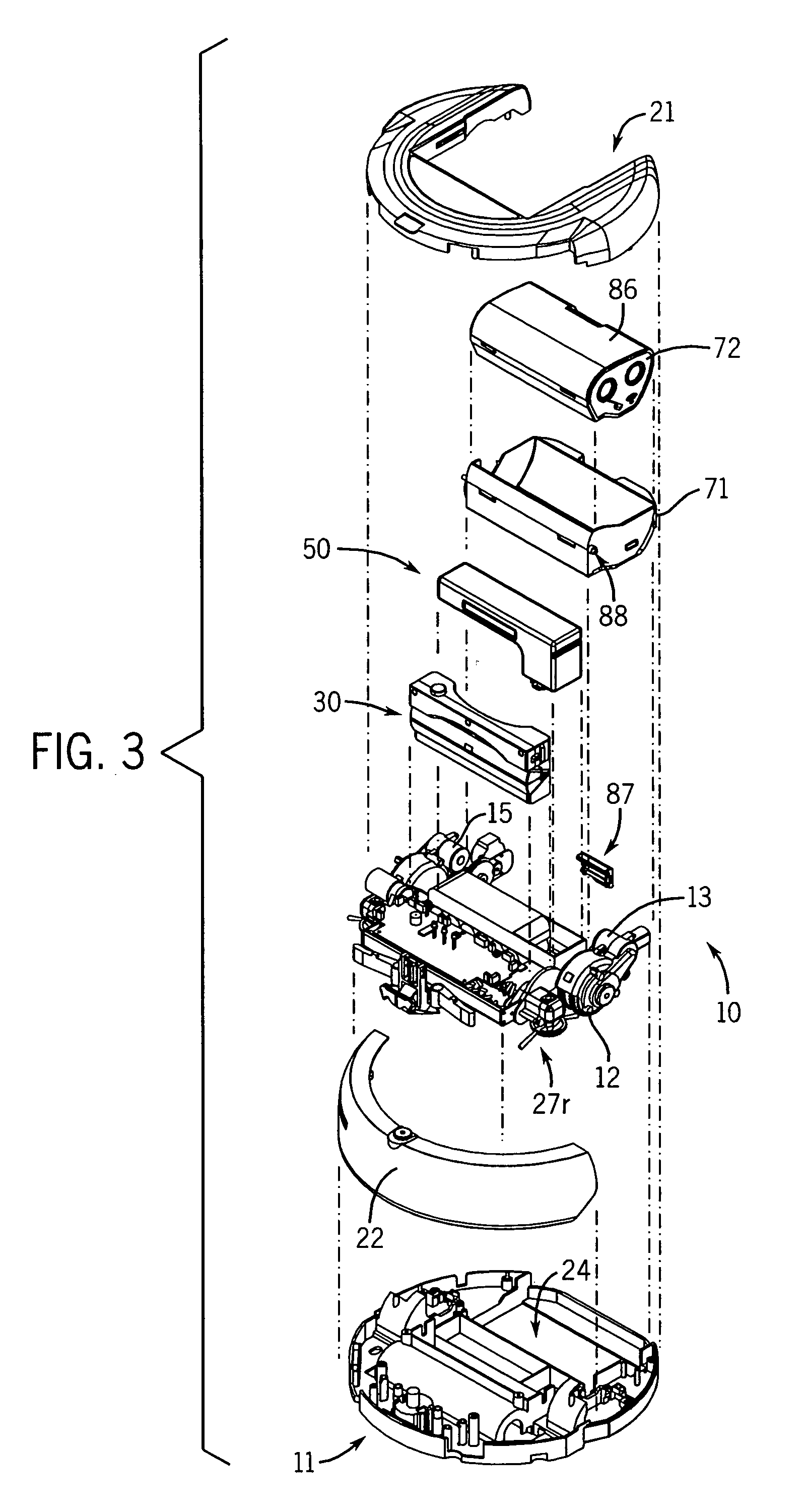
[0033]Referring to FIGS. 1-9, there is shown an autonomous robotic surface treating device 10 according to the invention. The robotic surface treating device 10 includes a housing 11 that supports a right wheel 12, a right wheel motor 13, a left wheel 14, a left wheel motor 15, a front center wheel 16, a top cover 21, and a bumper 22. The right wheel motor 13 and the left wheel motor 15 receive power from a bank of batteries 18 (see FIG. 8), and are under the control of a programmable controller (not shown).

[0034]An encoder may be associated with each wheel 12,14 and each encoder is connected to the controller. Encoders are commercially available and in one version, the encoder outputs a signal having a pulse every time each wheel 12,14 rotates a predetermined angle. The controller respectively calculates the wheel speed of each wheel 12,14 based upon an interval between pulses outputted from each encoder. Among other things, the controller can use calculated wheel speeds to control...


PUM


Abstract

A robotic surface treating device that can perform carpet sweeping, hard-surface dry sweeping / wiping, and hard-surface sweeping / mopping is disclosed. The robotic surface treating device includes a sweeper brush, a dust bin for collecting debris from the brush, a reel-to-reel sheet of cleaning material, and a fluid delivery system for delivering fluid from a fluid reservoir onto the sheet of cleaning material and / or onto the surface to be treated. The dust bin, reel-to-reel sheet of cleaning material, and the fluid reservoir are separately installed from the top of the device, and may be separately removed for replacement.

Description

CROSS REFERENCES TO RELATED APPLICATIONS[0001]Not applicableSTATEMENT REGARDING FEDERALLY SPONSORED RESEARCH / DEVELOPMENT[0002]Not applicableBACKGROUND OF THE INVENTION[0003]It is desirable to minimize the amount of human labor expended in maintaining and cleaning residential and commercial spaces. The art has therefore developed robotic devices that can clean or otherwise maintain or treat floors, carpeting or the like without the necessity for a human to be present during the operation of the device. The most common robotic devices of this kind are dusters, buffers, vacuum cleaners, floor sweepers, and floor polishers.[0004]Such devices typically have a computer control program to direct a preferred movement pattern. The control is linked to steering devices as well as motors that are in turn connected to wheels. Many of these devices also include sensors to confirm the initial and later positions of the device relative to the pre-set path. The most sophisticated of these devices i...

Claims


Application Information

Patent Timeline
Patent Type & Authority Patents(United States)
IPC IPC(8): A47L11/18A47L11/282
CPCA47L11/28A47L11/33A47L11/4047A47L11/4083A47L11/4036A47L2201/00
Inventor JAWORSKI, THOMASHARWIG, JEFFREY L.GIPP, MARK M.LARU, KATHLEEN M.CHEN, SEAKEECHENG, FUKYUENTAM, KAMFONG
Owner SC JOHNSON & SON INC
Learn More