Receiver including an oscillation circuit for generating an image rejection calibration tone

a technology of oscillation circuit and receiver, applied in the field of radio frequency communication system, can solve the problems of limiting the performance of the receiver, residual image frequency, and difficulty in implementing narrow-bandwidth bandpass filters

Active Publication Date: 2005-03-31
SILICON LAB INC
View PDF12 Cites 66 Cited by
  • Summary
  • Abstract
  • Description
  • Claims
  • Application Information

AI Technical Summary

Problems solved by technology

However, narrow-bandwidth bandpass filters become increasingly difficult and bulky to implement as their center frequencies increase.
However, imbalances in the gain and phase relationships between the two paths may yield imperfect image frequency cancellation, and thus result in a residual image frequency.
This residual image frequency may cause undesired interference that may limit the performance of the receiver.

Method used


Image

  • Receiver including an oscillation circuit for generating an image rejection calibration tone
  • Receiver including an oscillation circuit for generating an image rejection calibration tone
  • Receiver including an oscillation circuit for generating an image rejection calibration tone

Examples


Embodiment Construction

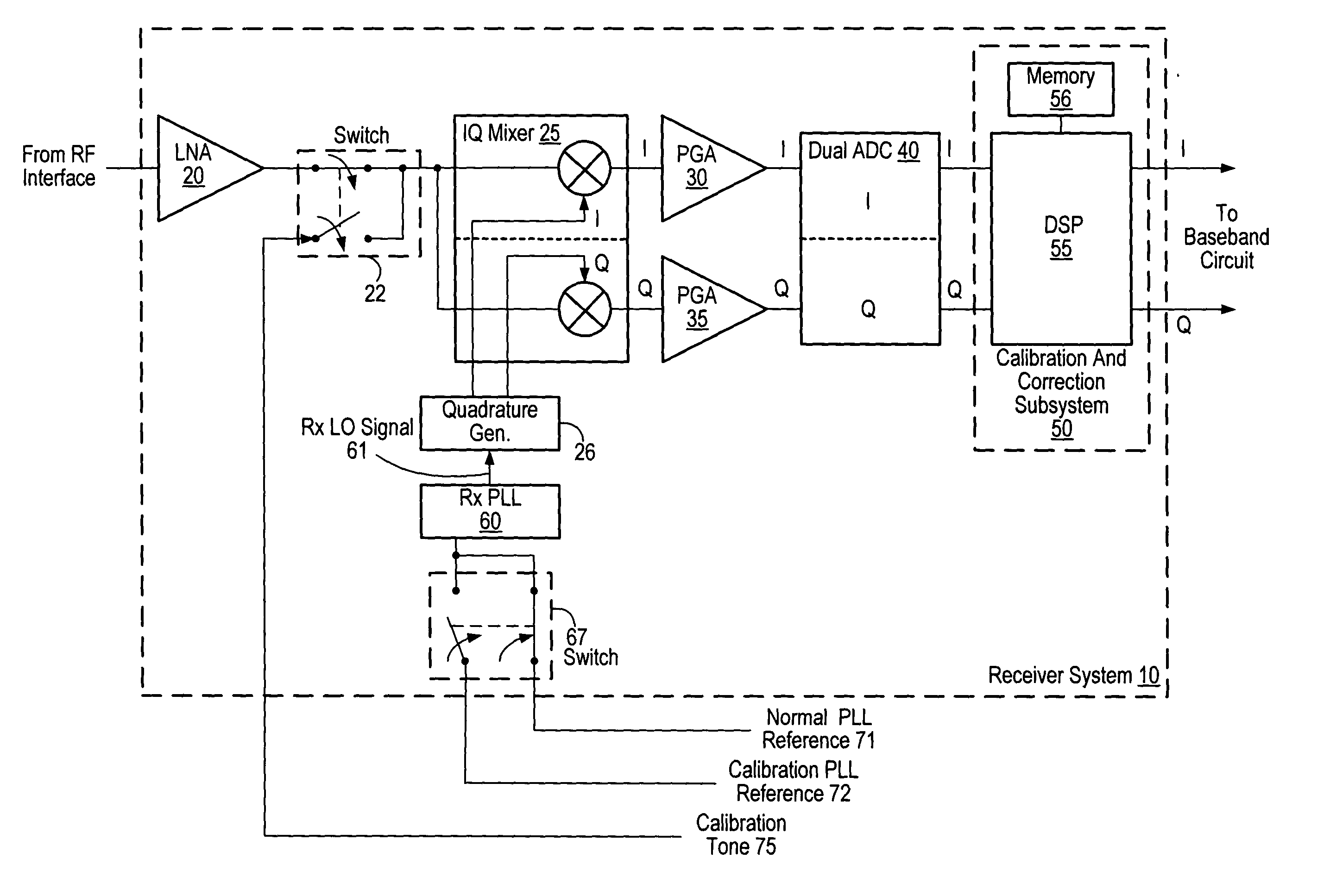
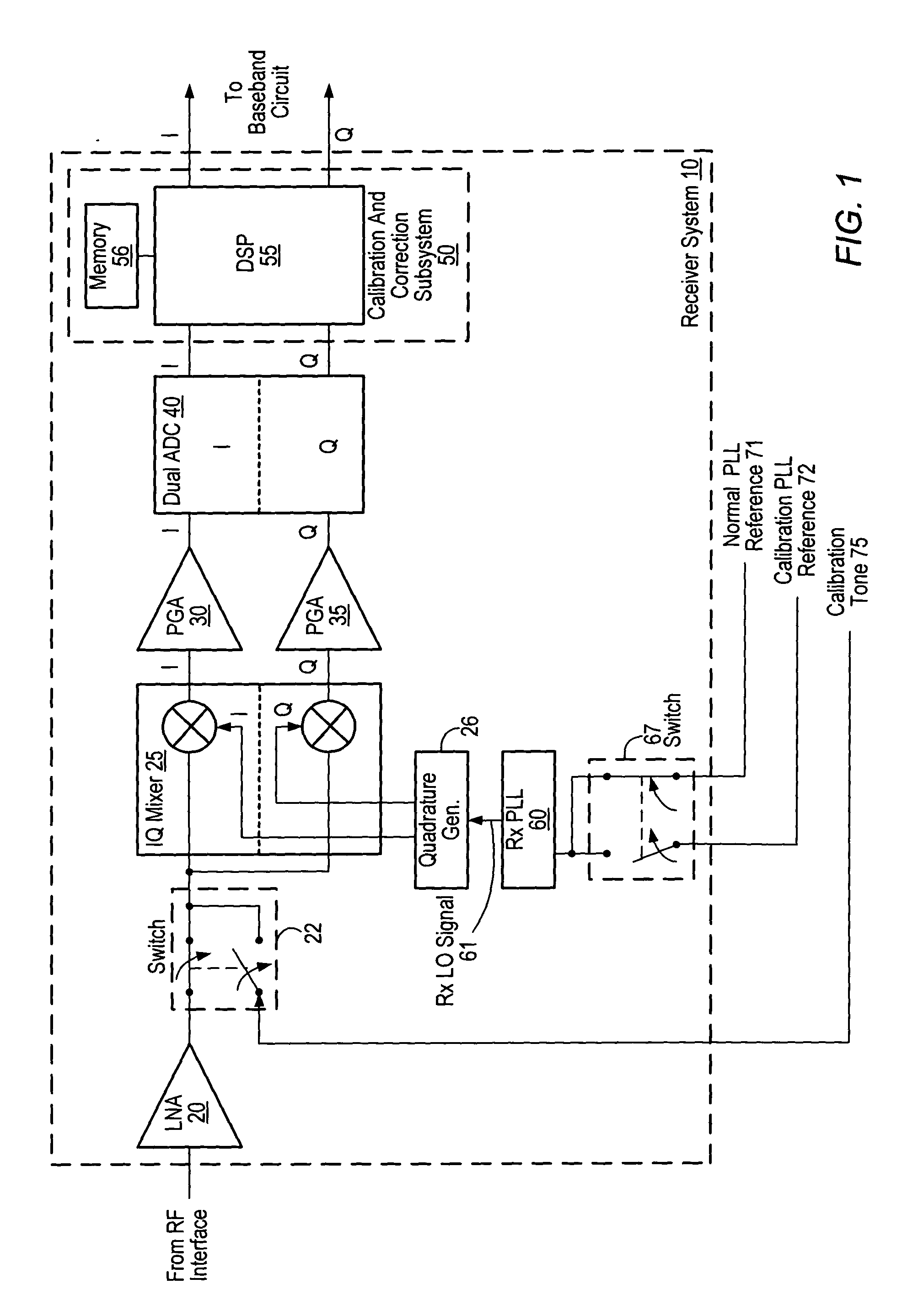
Turning now to FIG. 1, a block diagram of one embodiment of a receiver system 10 is shown. Receiver system 10 may be configured to operate within a wireless communication device, such as a cellular telephone handset or a wireless data modem, for example. In general, receiver system 10 may be configured to receive an incoming radio frequency (RF) signal from an RF interface (not shown), which may include elements such as an antenna, filters, switches, and amplifier stages. Receiver system 10 may also be configured to down-convert the frequency of the received RF signal and to provide the down-converted signal to a baseband circuit (not shown) for demodulation and decoding of the signal.

In some embodiments, receiver system 10 may be a subsystem of a transceiver that may further include a transmitter system (not shown in FIG. 1). Such a transmitter system may be configured to receive a modulated baseband signal from a baseband circuit and to generate a modulated carrier at the highe...


PUM


Abstract

A receiver circuit includes an oscillator circuit configured to generate a calibration tone and a phase locked loop (PLL) reference signal. An output frequency of the VCO may be divided by respective amounts to derive a desired calibration tone frequency and a desired PLL reference signal frequency. In addition to the oscillator circuit, the receiver circuit may further include a phase locked circuit configured to generate a PLL output signal that is phase locked in relation to the PLL reference signal. During a calibration mode, a quadrature generator may be used to generate quadrature mixer local oscillator signals dependent upon the PLL output signal, and an in-phase/quadrature mixer may be used to mix the calibration tone with the quadrature mixer LO signals.

Description

BACKGROUND OF THE INVENTION 1. Field of the Invention This invention relates to radio frequency communication systems including transceivers and, more particularly, to the generation of calibration tones for receiver image rejection calibration. 2. Description of the Related Art In many modern communication systems, information is transmitted and received by modulating a radio frequency (RF) carrier signal with a data signal and then demodulating the RF signal to recover the data signal. Demodulating an RF carrier signal usually involves tuning a receiver to the carrier signal, which may be at a substantially higher frequency than the frequencies of the data it conveys. For example, a carrier signal frequency may be on the order of 1-2 GHz, whereas the bandwidth of the data channel conveyed by the carrier-signal may be on the order of only 100-200 kHz. In one approach to demodulating an RF signal, a bandpass filter having a bandwidth approximately equal to the data channel band...

Claims


Application Information

Patent Timeline
Patent Type & Authority Applications(United States)
IPC IPC(8): H04B1/30
CPCH04B17/21H04B1/30
Inventor WILLINGHAM, SCOTT D.
Owner SILICON LAB INC
Why Eureka
Try Eureka