Image processing method and apparatus

a technology of image processing and apparatus, applied in the field of image processing methods and apparatuses, can solve the problems of easy adverse influence of dithering processing, not producing noticeable effects on images having a wide dynamic range, etc., and achieves the effect of reducing the number of pseudo grayscale levels in dithering processing, and reducing the number of pseudo grayscale levels

Inactive Publication Date: 2005-05-19
CANON KK
View PDF6 Cites 17 Cited by
  • Summary
  • Abstract
  • Description
  • Claims
  • Application Information

AI Technical Summary

Benefits of technology

[0033] According to the present invention, the number of pseudo grayscale levels in dithering processing is controlled according to the level of the dynamic range of an input image signal and the type of resolution conversion processing (enlargement or reduction). It is thus possible to perform signal processing so that high quality images can be displayed while effectively inhibiting pseudo contours.
[0034] More specifically, when the resolution conversion processing is enlargement processing, the number of pseudo grayscale levels in dithering processing is determined to be greater. When the level of the dynamic range of an input image signal is relatively narrow, the number of pseudo grayscale levels in dithering processing is determined to be greater. Accordingly, high quality images can be displayed while effectively inhibiting pseudo contours.
[0035] More preferably, the number of pseudo grayscale levels in the dithering processing is determined based on a combination of the level of the dynamic range of an image, the type of resolution conversion processing, and the level of edge enhancement processing. Accordingly, high quality images can be displayed while effectively inhibiting pseudo contours.

Problems solved by technology

In this case, however, dithering processing does not produce a noticeable effect on images having a wide dynamic range or images subjected to edge enhancement, since pseudo contours do not easily occur because of the low correlation between adjacent pixels of such images.
Conversely, dithering processing easily produces an adverse influence, for example, noise having a fixed pattern, which is noticeable.

Method used


Image

  • Image processing method and apparatus
  • Image processing method and apparatus
  • Image processing method and apparatus

Examples


first embodiment

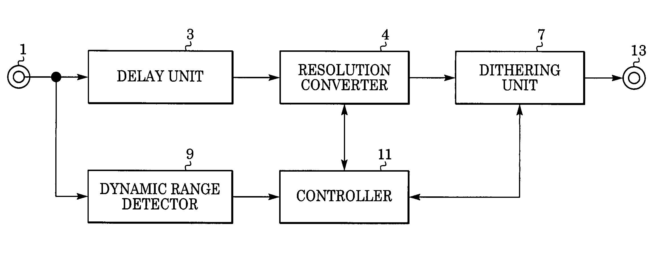
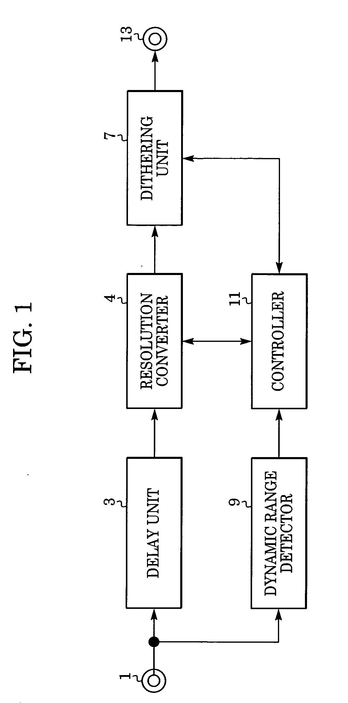
[0047] Referring to an image processing apparatus shown in FIG. 1, a digital image signal is input into an input terminal 1. In this embodiment, the input digital pixel signal is quantized with eight bits.

[0048] The digital image signal input into the input terminal 1 is then output to a delay unit 3 and a dynamic range detector 9.

[0049] In the delay unit 3, the digital pixel signal is delayed until the dynamic range of the image signal is detected in the dynamic range detector 9.

[0050] The dynamic range of the image signal in the dynamic range detector 9 may be detected as follows. The absolute value of the difference between the maximum value and the minimum value of the pixel signal in one frame of the input image signal is determined. Then, after comparing the determined absolute value with a predetermined threshold, the dynamic range of the image signal is found to be relatively wide or narrow.

[0051] The delayed digital image signal is then output to a resolution converter ...

second embodiment

[0085]FIG. 5 is a block diagram illustrating another example of a configuration of an image processing apparatus using the image processing method according to another embodiment of the present invention.

[0086] A digital image signal is input into an input terminal 501. In this embodiment, an input digital pixel signal is quantized with eight bits.

[0087] The digital pixel signal input into the input terminal 501 is output to a delay unit 503 and a dynamic range detector 511.

[0088] In the delay unit 503, the digital image signal is delayed until the dynamic range of the image signal is detected in the dynamic range detector 511. For example, to detect the dynamic range of one frame of a television signal, the delay unit 503 delays the television signal by one frame. The delayed digital image signal is output to a resolution converter 505.

[0089] The resolution converter 505 converts the resolution of the input signal to the resolution of a display device, such as the number of pix...


PUM

PropertyMeasurementUnit
grayscaleaaaaaaaaaa
frequencyaaaaaaaaaa
high-frequencyaaaaaaaaaa

Abstract

An image processing method includes the steps of detecting a dynamic range of input image data, performing resolution conversion processing to increase the number of grayscale levels of the input image data, and performing dithering processing to reduce the number of grayscale levels of each pixel of the input image data. The number of pseudo grayscale levels in the dithering processing is determined, based on a parameter indicating the level of the dynamic range and a parameter concerning the resolution conversion processing.

Description

BACKGROUND OF THE INVENTION [0001] 1. Field of the Invention [0002] The present invention relates to image processing methods and apparatuses, and more particularly, to a method for processing digital image signals. [0003] 2. Description of the Related Art [0004] Thin display devices, liquid crystal displays (LCDs), plasma displays (PDPs), and field emission displays (FEDs) have attracted attention. [0005] The LCDs, PDPs, and FEDs are fixed-pixel matrix-driven display devices, which can be driven by digital image signals. The number of grayscale levels of the above-described display devices is represented by the number of bits of a video signal corresponding to each pixel. [0006] Techniques for displaying images so that they can be visually aesthetic to the human eye by performing signal processing on image signals are being considered. Such techniques include edge enhancement processing for enhancing edge portions and high-frequency components of images so as to apparently increase...

Claims


Application Information

Patent Timeline
Patent Type & Authority Applications(United States)
IPC IPC(8): G06T5/00G03F3/08G06F15/00G06T5/40G09G5/391H04N1/387H04N1/405H04N5/14H04N5/205
CPCG06T5/009G09G2340/0428G09G3/2051G06T5/40
Inventor HOSHI, NOBUHIRO
Owner CANON KK
Why Eureka
Try Eureka