Multi-position rail for a barrier

a multi-position rail and barrier technology, applied in the field of rails, can solve the problems of increasing the difficulty of providing proper inventory of barrier components, affecting the use of particular upright members, and affecting the quality of the barrier,

Inactive Publication Date: 2005-06-23
KROY BUILDING PROD
View PDF27 Cites 34 Cited by
  • Summary
  • Abstract
  • Description
  • Claims
  • Application Information

AI Technical Summary

Problems solved by technology

Rails made of durable materials often have a more attractive appearance, but may be more difficult to cut or otherwise shape into condition for use with a particular upright member.
Moreover, cutting of the rails to accommodate the upright members may weaken the rails.
The use of a different design for top rails as compared to bottom rails may increase the difficulty in providing proper inventory of barrier components.
Also, the need to accommodate upright members of various different shapes and spacings may increase the amount of inventory of components required, and may also increase the difficulty and cost of installing the barrier.

Method used


Image

  • Multi-position rail for a barrier
  • Multi-position rail for a barrier
  • Multi-position rail for a barrier

Examples


Embodiment Construction

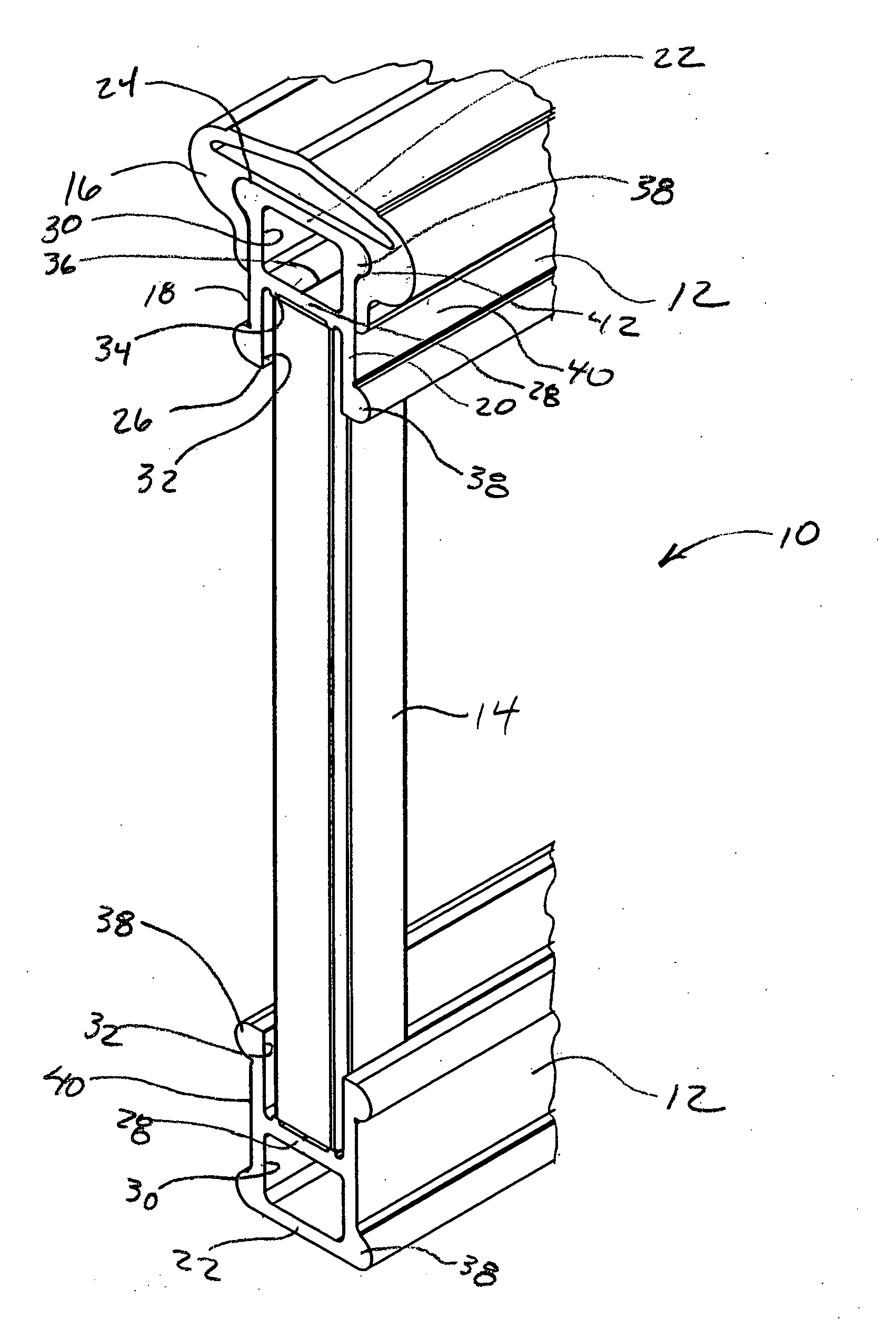
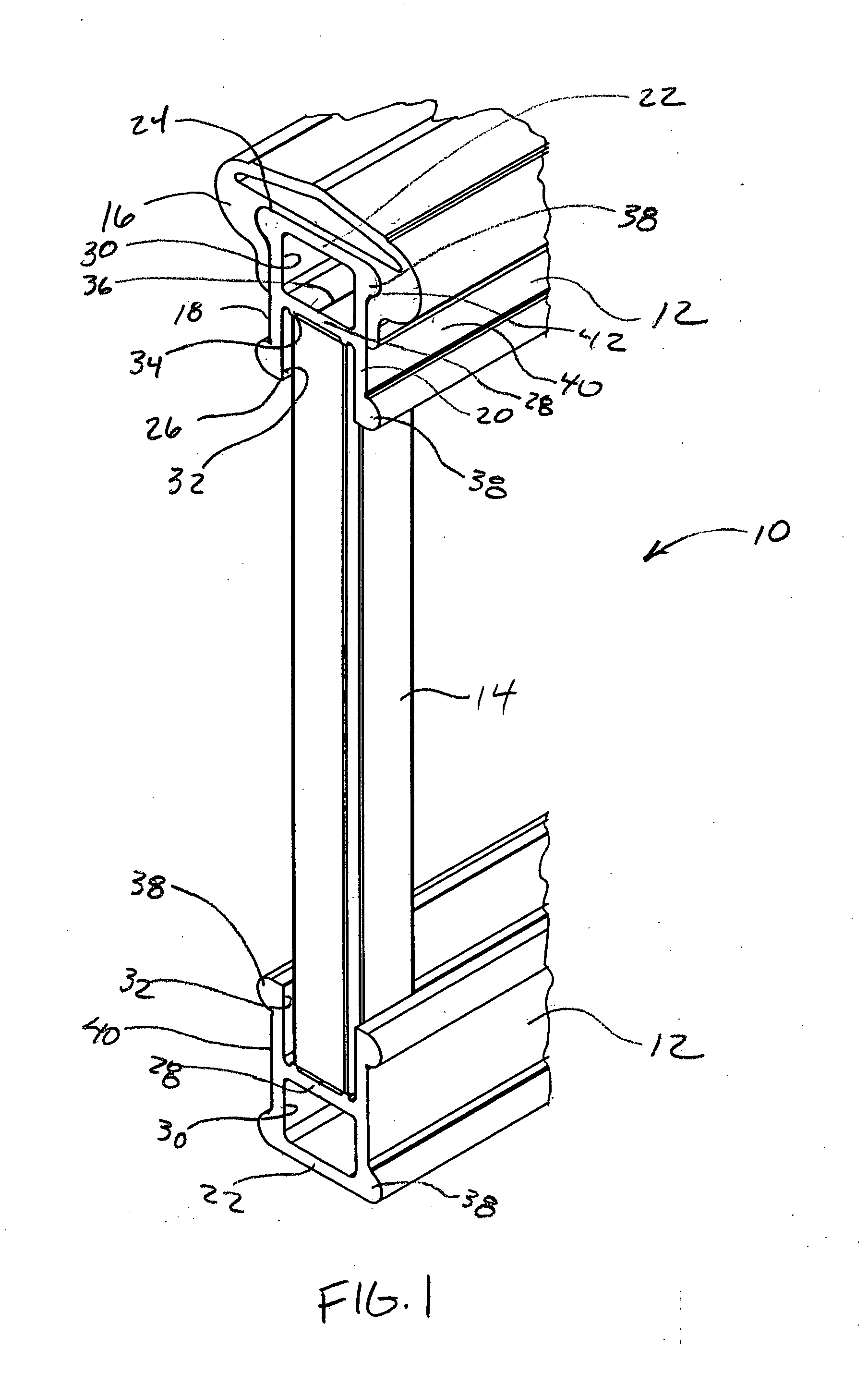
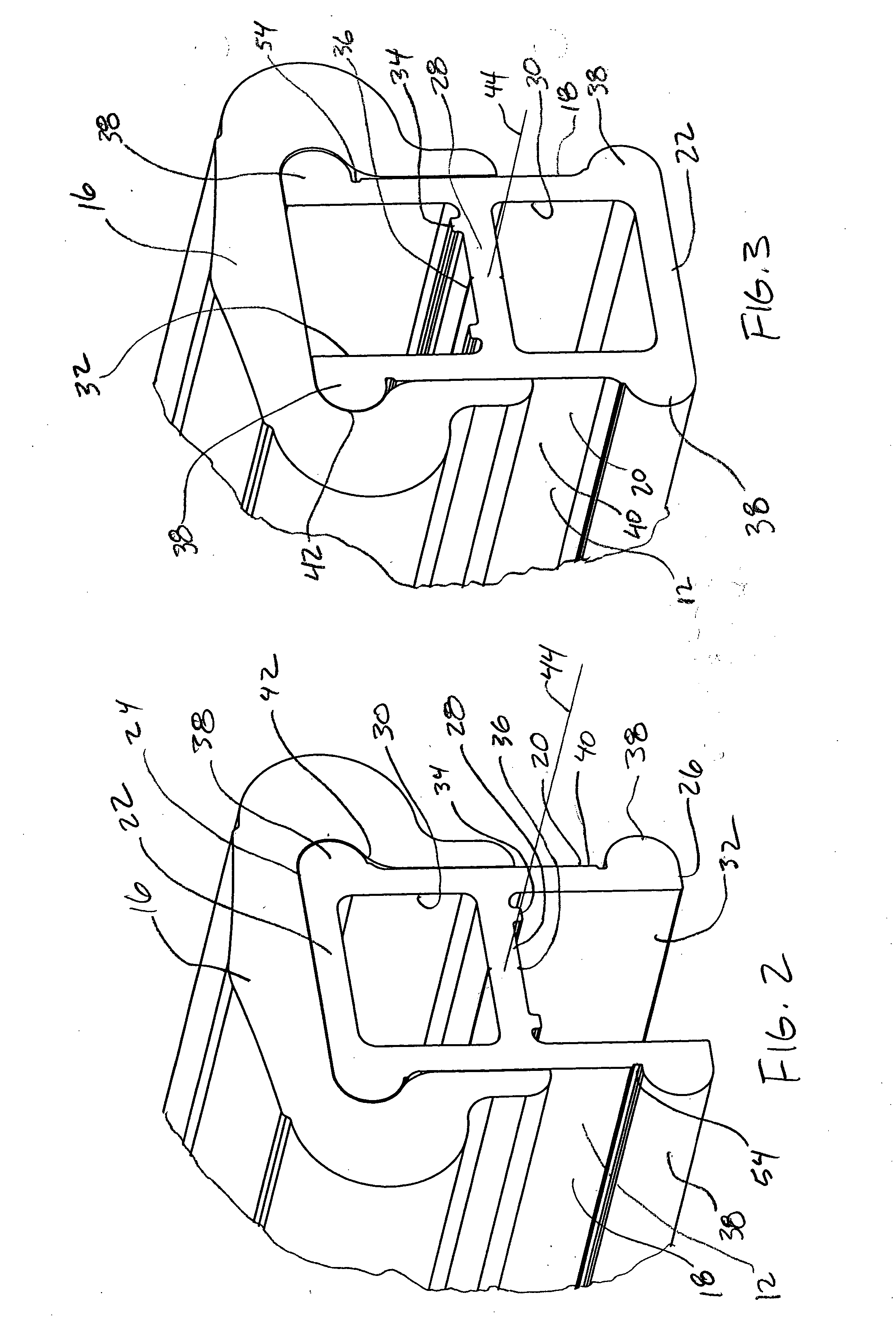
[0029] For the purposes of promoting an understanding of the principles in accordance with the disclosure, reference will now be made to the embodiments illustrated in the drawings and specific language will be used to describe the same. It will nevertheless be understood that no limitation of the scope of the disclosure is thereby intended. Any alterations and further modifications of the inventive features illustrated herein, and any additional applications of the principles of the disclosure as illustrated herein, which would normally occur to one skilled in the relevant art and having possession of this disclosure, are to be considered within the scope of the disclosure claimed.

[0030] It must be noted that, as used in this specification and the appended claims, the singular forms “a,”“an,” and “the” include plural referents unless the context clearly dictates otherwise.

[0031] In describing and claiming the present disclosure, the following terminology will be used in accordanc...


PUM


Abstract

A rail is disclosed for use in forming a barrier system, such as a railing for a deck, porch, walkway or fence. The rail has a versatile configuration in that either a top or bottom side of the rail may be received in a rail cover. The rail may have side walls and a cross wall on the top or bottom side of the rail. A channel may be formed on the side of the rail opposite the cross wall. Upright members, such as pickets, planks, balusters, or walls may be received in either the top side or the bottom side of the rail, in the channel or through the cross wall. A cap having openings for receiving the upright member may be placed on the channel. The rail may be positioned on the top or bottom of the barrier system and the rail may be symmetrical to provide an aesthetically pleasing appearance.

Description

CROSS-REFERENCE TO RELATED APPLICATIONS [0001] This application is a continuation-in-part of U.S. patent application Ser. No. 10 / 764,333, filed Jan. 23, 2004, entitled “MULTI-POSITION RAIL FOR A BARRIER,” which claimed the benefit of U.S. Provisional Application Ser. No. 60 / 473,535, filed May 26, 2003, which applications are hereby incorporated by reference herein in their entireties, including but not limited to those portions that specifically appear hereinafter, the incorporation by reference being made with the following exception: In the event that any portion of the above-referenced applications is inconsistent with this application, this application supercedes said above-referenced applications.STATEMENT REGARDING FEDERALLY SPONSORED RESEARCH OR DEVELOPMENT [0002] Not Applicable. BACKGROUND [0003] 1. The Field of the Invention [0004] The present disclosure relates generally to rails, and more particularly, but not exclusively, to rails that can be used in various positions an...

Claims


Application Information

Patent Timeline
Patent Type & Authority Applications(United States)
IPC IPC(8): E04F11/18
CPCE04F2011/1897E04F11/1836E04F2011/1821E04F2011/1827
Inventor FORBIS, JOHN T.KALTENBACH, ROY H.
Owner KROY BUILDING PROD
Why Eureka
Try Eureka