Automotive air conditioner

Active Publication Date: 2009-03-12
HIGHLY MARELLI JAPAN CORPORATION
View PDF25 Cites 8 Cited by
  • Summary
  • Abstract
  • Description
  • Claims
  • Application Information

AI Technical Summary

Benefits of technology

[0011]The present invention has been made in view of the above problems, and an object of the present invention is to provide an automotive air

Problems solved by technology

However, in the conventional techniques described in JP2001-113931A and JP2002-307929A, the air is distributed to the foot outlet by advancing a half of the foot door, so the cold air from the cold air path and the warm air from the warm air pa

Method used


Image

  • Automotive air conditioner
  • Automotive air conditioner
  • Automotive air conditioner

Examples


embodiment 1

[0030]At first, the structure of Embodiment 1 will be described with reference to FIGS. 1-8.

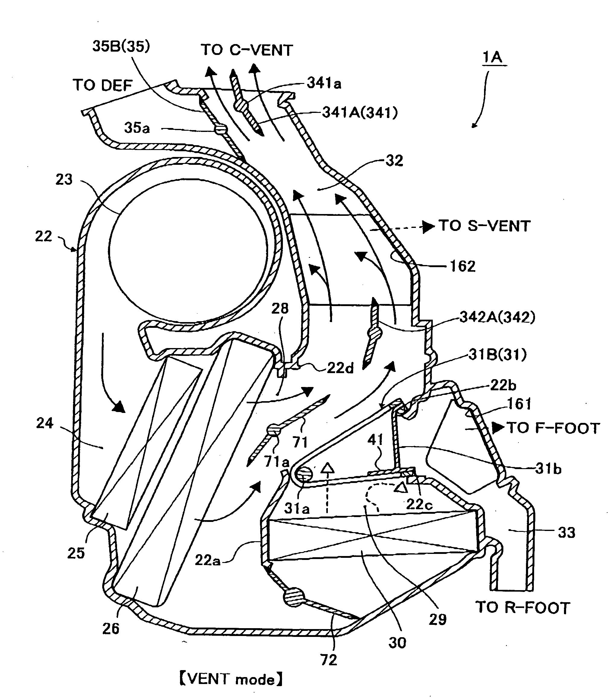
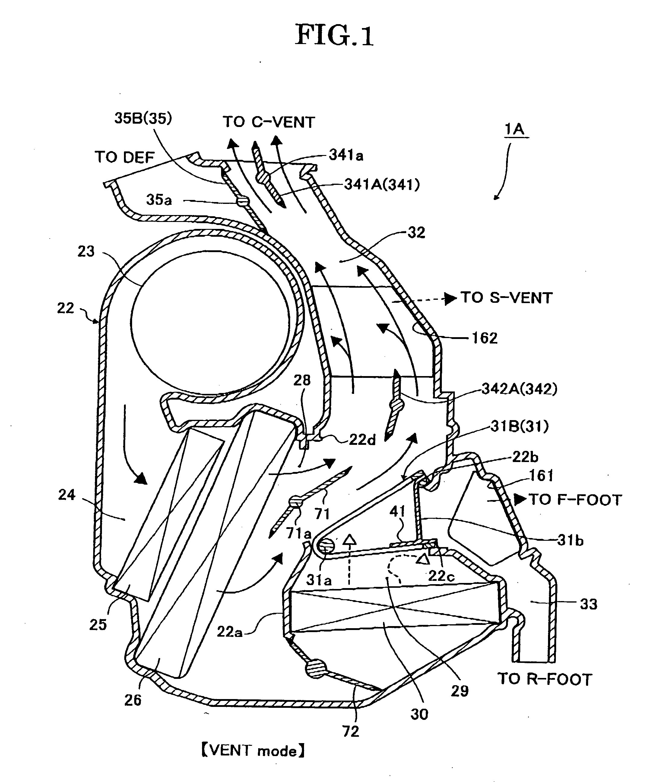
[0031]In an automotive air conditioner 1A according to Embodiment 1, an air passageway is formed by appropriately zoning the inside area of an air-conditioning case made of a systematic resin or the like with a wall 22a or the like, and the quality of the air such as the cleanness and the temperature is adjusted by air distribution members (blower 23, introduction path 24) disposed in the upstream positions of this air passageway, functional members (filter 25, evaporator 26, heater core 30, etc.) disposed in the air passageway, a cold air side air mix door 71, and a warm air side air mix door 72. The outlets (blowing modes) of the adjusted air can be changed by opening and closing positions of a center vent door 341, a side vent door 342, a def door 35, and a foot door 31.

[0032]The air discharged from the blower 23 is cleaned by passing through the filter 25 disposed in the introduction path...

embodiment 2

[0097]Embodiment 2 is an example in which a warm air path blocking plate for blocking a part of the warm air passageway in a state in which at least the foot door 31 is in the withdrawal position is integrally formed with the air-conditioning case

[0098]At first, the structure will be described with reference to FIGS. 11, 12.

[0099]A warm air path blocking plate 42 in an automotive air conditioner 1B according to Embodiment 2 is integrally formed with an air-conditioning case 22 as illustrated in FIGS. 11, 12, relative to the warm air path blocking plate 41 according to Embodiment 1 integrally formed with the foot door 31. More particularly, the warm air blocking plate 42 is integrally formed to extend from the end portion of a first foot opening seal face 22c of the air-conditioning case 22 with which a sealing face 37a in the end portion of the circumference direction in the front side of the advanced direction of the foot door 31 has contact. In addition, other structures are the s...

embodiment 3

[0107]Embodiment 3 is an example in which a warm air path blocking door is provided for a higher heat pick-up improvement performance, in addition to the structure of Embodiment 1.

[0108]At first, the structure will be described with reference to FIG. 13.

[0109]In an automotive air conditioner IC according to Embodiment 3, the door shaft 31a of the foot door 31 includes concentric double shafts. One shaft 43a of the concentric double shafts is provided with a warm air path blocking door 43 for blocking the opening space of the warm air path, which is not blocked by the warm air path blocking plate 41 when the door is closed (when the vent mode is selected in the full cool mode), and for opening the opening space of the warm air path when the door is open (except when the vent mode is selected in the full cool mode). In addition, other structures of Embodiment 2 are similar to the structures of Embodiment 1, so the same reference numbers are given to the corresponding structures to omi...


PUM


Abstract

An automotive air conditioner includes an air-conditioning case in which air passageways having a cold air path via an evaporator, a warm air path via a heater core, and a plurality of discharge path systems communicating with outlets, respectively, are formed, an air mix door which distributes cold air and warm air by an opening degree to each of the discharge path systems via a junction region of the cold air and the warm air, and a rotary door having a cross wall, which is rotatably disposed in the junction region of the cold air and the warm air and blocks air flow from the junction region to the downstream side by the cross wall in an advanced position, the rotary door and the air mix door including an overlap layout which uses a door space inside the cross wall of the rotary door in the advanced position as an opening and closing operation space of the air mix door.

Description

PRIORITY CLAIM[0001]The present application is based on and claims priority from Japanese Patent Application No. 2007-170353, filed on Jun. 28, 2007, the disclosure of which is hereby incorporated by reference in its entirety.BACKGROUND OF THE INVENTION[0002]1. Field of the Invention[0003]The present invention relates to an automotive air conditioner which blows out, inside a vehicle, air in which a temperature is adjusted to a desired temperature by mixing cold air with warm air.[0004]2. Description of the Related Art[0005]There is known a conventional automotive air conditioner in which an air passageway including a cold air path via an evaporator, a warm air path via a heater core, and a plurality of discharge paths which communicates with blowing outlets (def outlet, vent outlet, foot outlet), respectively, is formed inside an air-conditioning case, and cold air and warm air distributed by an opening degree of an air mix door flow to each of the discharge paths via a junction re...

Claims


Application Information

Patent Timeline
IPC IPC(8): B60H1/32
CPCB60H1/00685
Inventor ONDA, MASAHARUTSUKUDA, RYUJIYANASHIMA, HIROMICHI
Owner HIGHLY MARELLI JAPAN CORPORATION
Why Eureka
Try Eureka