
Dust collecting mechanism

a technology of dust collecting mechanism and air pump, which is applied in the direction of auxillary pretreatment, positive displacement liquid engine, separation process, etc., can solve the problems of lowering the performance and the function of the pump, and achieve the effect of simple assembly work

Inactive Publication Date: 2010-09-28
TECHNO TAKATSUKI
View PDF36 Cites 9 Cited by
  • Summary
  • Abstract
  • Description
  • Claims
  • Application Information

AI Technical Summary

Benefits of technology

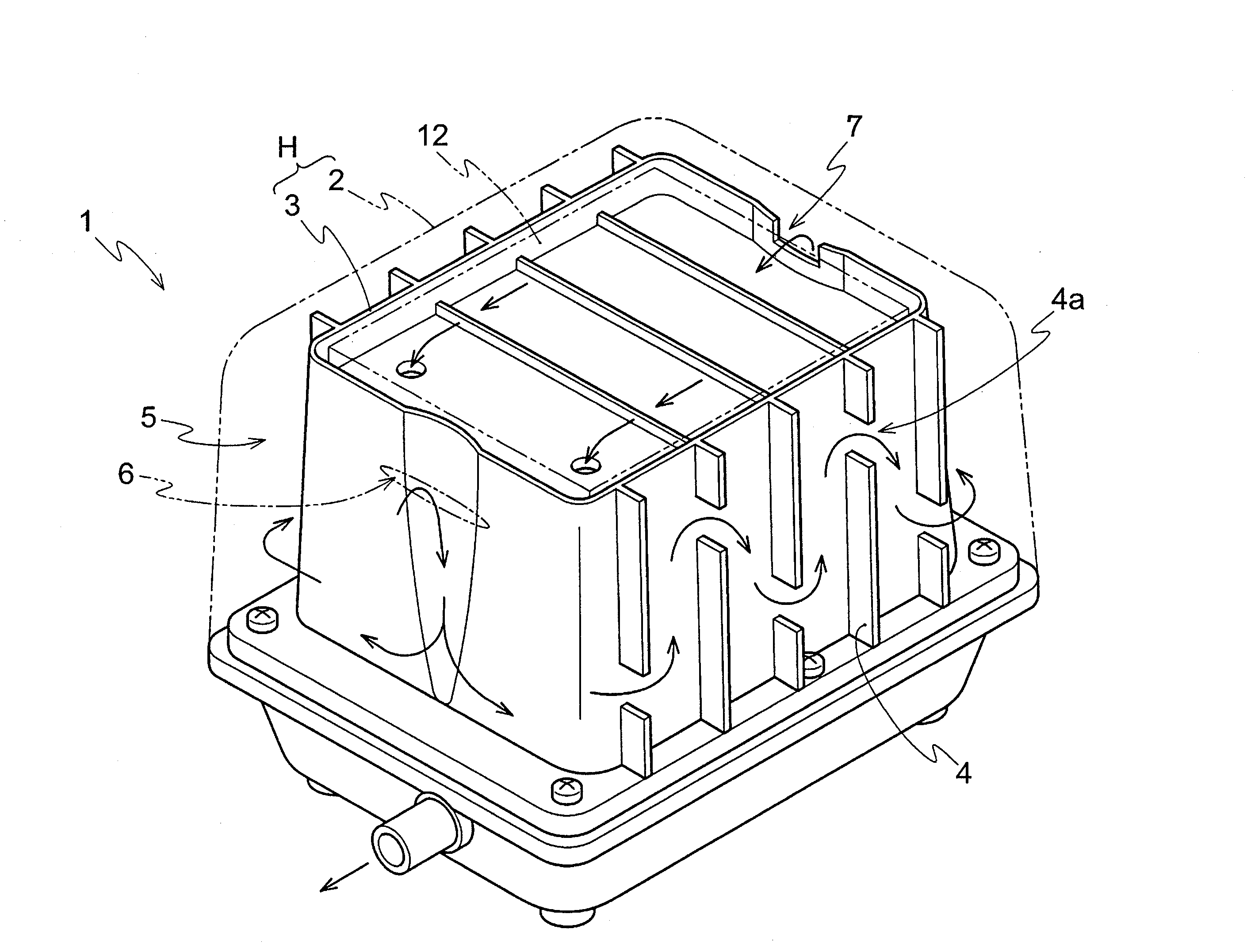
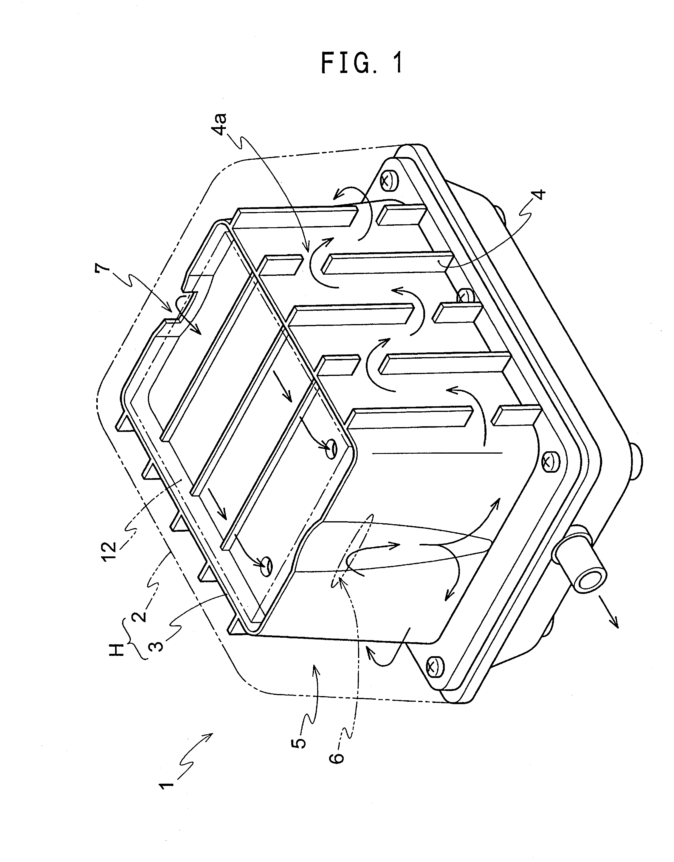
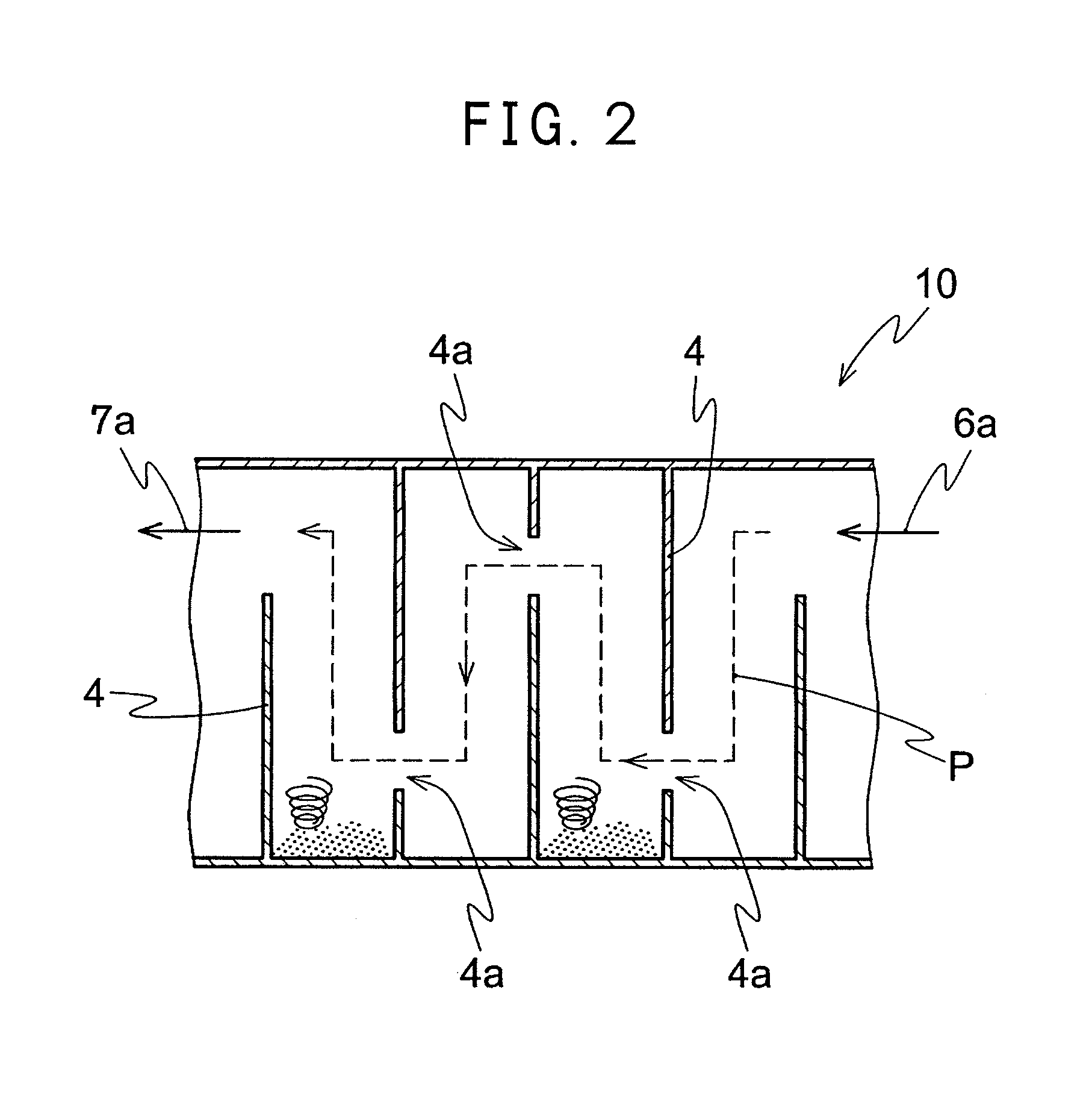
"The present invention provides a dust collecting mechanism for an air pump that has a compact structure, can realize the efficiency of dust collecting ability, is simple in assembly work, and can reduce cost. The mechanism includes a housing with a barrier chamber and a plurality of cross walls at which vent holes are provided. The position of the vent hole of the adjacent cross wall is different among the cross walls. The mechanism can demarcate the obstacle of the vent channel in a zigzag direction and can function as a heat release means and a noise reduction means. The mechanism can achieve dust collecting action by the gravity and dropping of dust caused by the generation of the turbulent flow. The zigzag vent channel satisfies the protective grade requirements and a compact structure can be realized."

Problems solved by technology

Further, in case of piston type and diaphragm type electromagnetic vibrating pumps, the lowering of performance and the lowering of pump function caused by the abrasion and damage of a piston, the breakage of diaphragm and the damage of a valve dominate the life of the pump.

Method used


Image

  • Dust collecting mechanism
  • Dust collecting mechanism
  • Dust collecting mechanism

Examples


embodiment 1

[0060]As shown in FIG. 8, a container composed of 5 cells partitioned by the four cross walls or vessels 4 and linked by the vent holes 4a in which the 5 cells were alternately arranged was prepared. In FIG. 8, members shown by the reference code 8 were deflection plates and the deflection plates 8 were slanted by an angle θ (θ=25°) against the cross vessels 4 so as to approach to the vent holes 4a.

[0061]Further, as a result of flowing air contaminated with dust from the inlet 6, it was cleared that there were fears of:

[0062]that the generation of vortex is little in the cell having the deflection plates 8;

[0063]that dust goes over the deflection plates 8; and

[0064]that dust is easily accumulated in a cell where the outlet 7 was provided and the dust flows out from the outlet 7 to the pump.

embodiment 2

[0065]As shown in FIG. 9, a container composed of 5 cells partitioned by the four cross walls or vessels 4 and linked by the vent holes 4a in which the 5 cells were alternately arranged was prepared. In FIG. 9, members shown by the reference code 8 were deflection plates and both of the deflection plates 8b of upper side and the deflection plates 8b of lower side were slanted by an angle θ (θ=45°) against the cross walls or vessels 4 so as to leave from the vent holes.

[0066]Further, as a result of flowing air contaminated with dust from the inlet 6, the deflection plates 8b were provided at the lower side, but they can be also respectively provided at the upper and lower portions in FIG. 9. It was cleared that the drifts 9 were generated at the lower side of the deflection plates 8b.


PUM

PropertyMeasurementUnit
wave curve shapeaaaaaaaaaa
flow rateaaaaaaaaaa
shapeaaaaaaaaaa

Abstract

A dust collecting mechanism for an air pump, in particular, an electromagnetic vibrational pump having a compact structure, capable of realizing the efficiency of dust collecting ability is disclosed. The mechanism is simple in assembly work. An inlet and an outlet for fluid are provided in the mechanism at a barrier chamber of the mechanism provided in at least one portion of a housing. A plurality of cross walls at which 1 or 2 or more of vent holes are provided are arranged in the mechanism. At least the position of the vent hole of the adjacent cross wall is different among a plurality of the cross walls.

Description

BACKGROUND OF THE INVENTION[0001]The present invention relates to a dust collecting mechanism for an air pump. More specifically, the present invention relates to the dust collecting mechanism for an electromagnetic vibrating air pump that is mainly utilized for supplying oxygen to a home septic tank and a water bath for fish culture. However, the dust collecting mechanism of the present invention is not limited to application to specific type air pump (electromagnetic vibrating air pump) but can be applied to a general air pump.[0002]As a pump related to a conventional technology, a diaphragm pump shown in FIGS. 17 and 18 is disclosed (refer to Japanese Unexamined Patent Publication No. 2004-76727). Further, the diaphragm pump of FIG. 18 is constituted with an electromagnet arranged facing a frame in a pump housing 200, a transducer equipped with a permanent magnet, a diaphragm linked with the both end of the transducer and a pump casing portion respectively fixed at both end sides...

Claims


Application Information

Patent Timeline
Patent Type & Authority Patents(United States)
IPC IPC(8): B01D45/00
CPCB01D45/06B01D45/08F04B45/047F04B45/043F04B39/16F04D29/70
Inventor KAWASAKI, NOZOMU
Owner TECHNO TAKATSUKI
Learn More