Display device

Inactive Publication Date: 2005-06-30
SEIKO EPSON CORP
View PDF11 Cites 20 Cited by
  • Summary
  • Abstract
  • Description
  • Claims
  • Application Information

AI Technical Summary

Benefits of technology

[0018] With this configuration, if for example, the second display section and the touch panel are arranged in front of the first display section so that the first display section is visible through the second display section and the touch panel, the first display section is allowed to retain the display

Problems solved by technology

However, with this conventional technique, since the charged grains are adsorbed to the transparent electrode to display the image, for example, the adsorption of the charged grains requires a long time, resulting

Method used


Image

  • Display device
  • Display device
  • Display device

Examples


Embodiment Construction

[0032] With reference to the drawings, description will be given of an example of an electronic book reader configured to browse the contents of electronic books as an embodiment of an image display device according to the present invention.

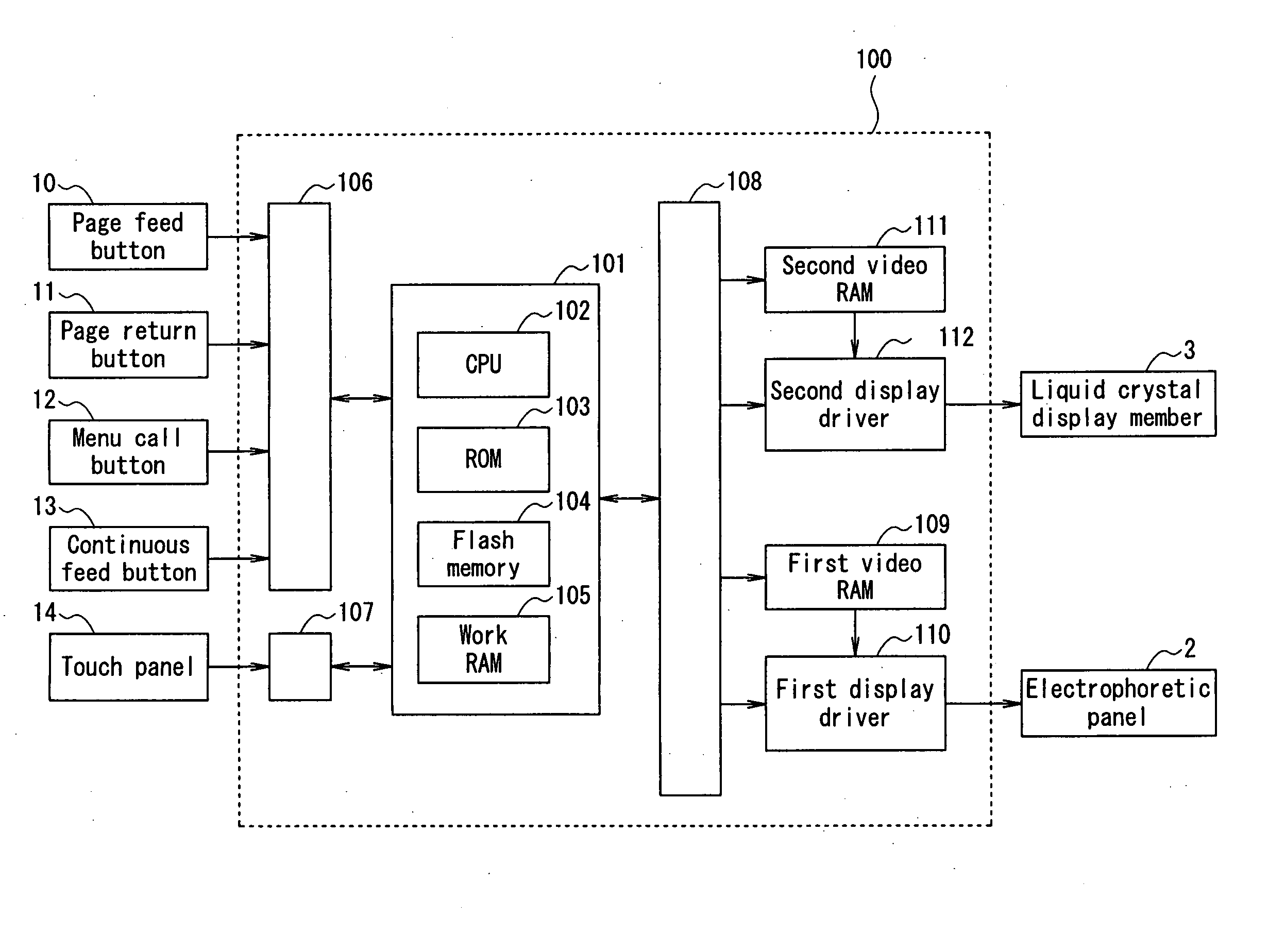
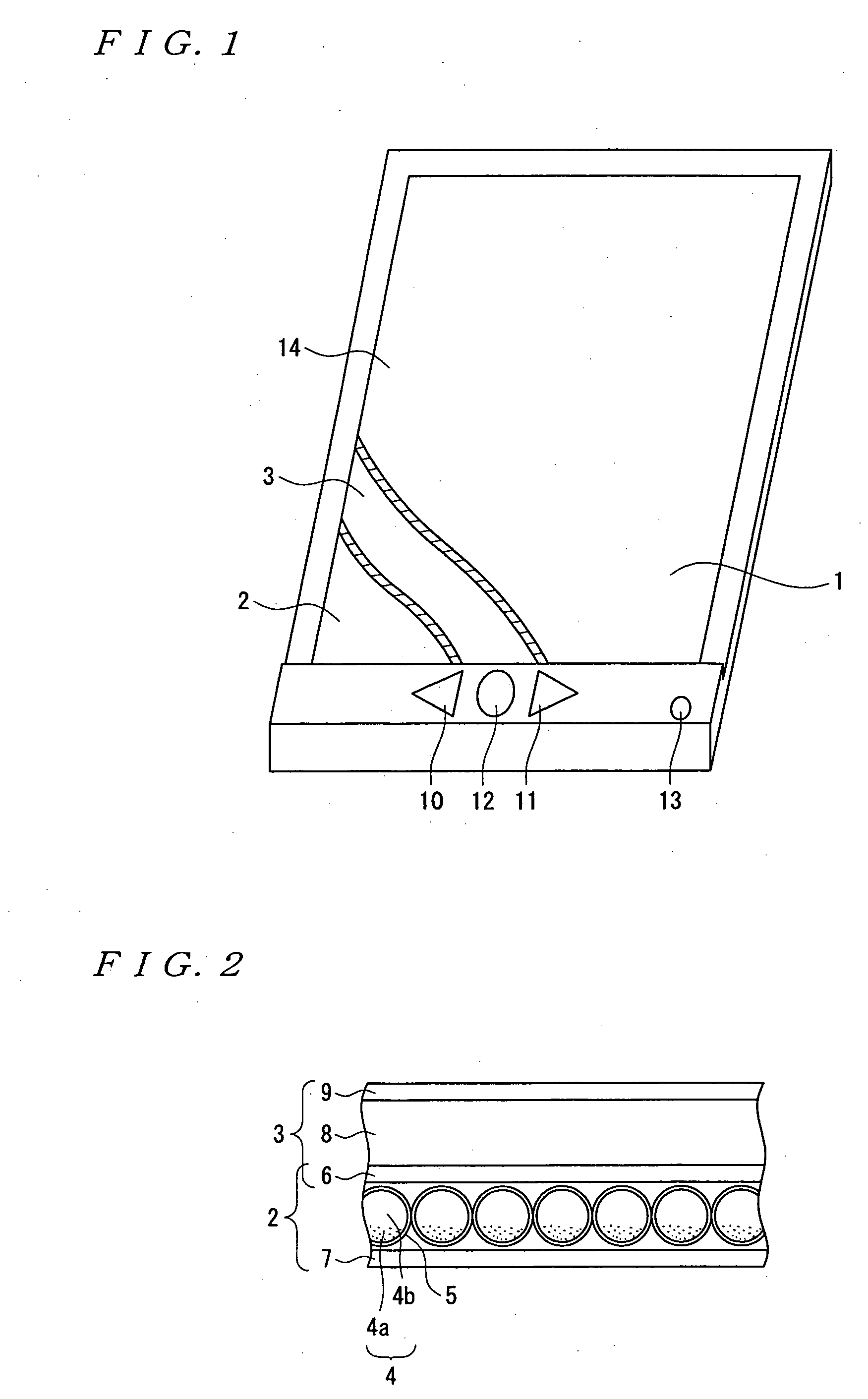
[0033]FIG. 1 is a schematic diagram showing the configuration of an electronic book reader that is an embodiment of the present invention. The electronic book reader has a display screen 1 in the center of the device which displays the contents of an electronic book divided into predetermined pages as shown in FIG. 1. Further, the display screen 1 has an electrophoretic display member 2 in the rear and a liquid crystal display member 3 in the front as shown in FIG. 2.

[0034] Further, the electrophoretic display member 2 includes a plurality of microcapsules 5 each containing an electrophoretic fluid dispersion 4 consisting of black charged grains 4a and a white dispersing medium 4b, and paired electrodes (a transparent electrode and a nontranspa...


PUM


Abstract

An image display device according to the present invention includes an electrophoretic display member 2 that can display a predetermined image, a liquid crystal display member 3 placed in front of the electrophoretic display member 2 and which can display the predetermined image at a higher speed than the electrophoretic display member 2, and a control device that causes the electrophoretic display member 2 and the liquid crystal display member 3 to display the image corresponding to the same image data at the same position as viewed from front of the device. The control device makes the liquid crystal display member 3 transparent after the predetermined image has been displayed in the electrophoretic display member 2.

Description

BACKGROUND OF THE INVENTION [0001] 1. Field of the Invention [0002] The present invention relates to an image forming device comprising a display section that can display a predetermined image. [0003] 2. Description of the Related Art [0004] As a technique of this kind, an image display device has hitherto been known which comprises an electrophoretic display member having a plurality of microcapsules each containing an electrophoretic fluid dispersion 4 consisting of black charged grains and a white dispersing medium and paired electrodes (for example, a transparent electrode and a nontransparent electrode) arranged so as to sandwich between the electrodes a layer in which the plurality of microcapsules are disposed as described in, for example, Japanese Patent Laid-Open No. 2000-35598. [0005] In such an image display device, in general, the potential of the transparent electrode is set at a high level, while the potential of the nontransparent electrode is set at a low level. The ...

Claims


Application Information

Patent Timeline
IPC IPC(8): G06F3/14G09G3/20G09G3/34G09G3/36
CPCG06F3/1431G09G3/2092G09G3/344G09G3/3611G09G2330/021G09G2300/0486G09G2320/0252G09G2320/103G09G2300/023
Inventor SAWADA, MUNENORIHIRAMATSU, KAZUNORINISHIZAWA, MASATO
Owner SEIKO EPSON CORP
Why Eureka
Try Eureka