Stress redistributing cable termination

a cable termination and stress redistributing technology, applied in the direction of cable fittings, electrical cable installations, belts/chains/gearrings, etc., can solve the problems of limitation of prior art design, excessive shearing stress on the surface bond, and undesirable stress concentration

Inactive Publication Date: 2005-08-11
BRIGHT TECH CO LTD
View PDF2 Cites 12 Cited by
  • Summary
  • Abstract
  • Description
  • Claims
  • Application Information

AI Technical Summary

Problems solved by technology

As mentioned previously, the seating process places considerable shearing stress on the surface bond, which often breaks.
This stress concentration is undesirable, and represents a limitation of the prior art design.

Method used


Image

  • Stress redistributing cable termination
  • Stress redistributing cable termination
  • Stress redistributing cable termination

Examples


Embodiment Construction

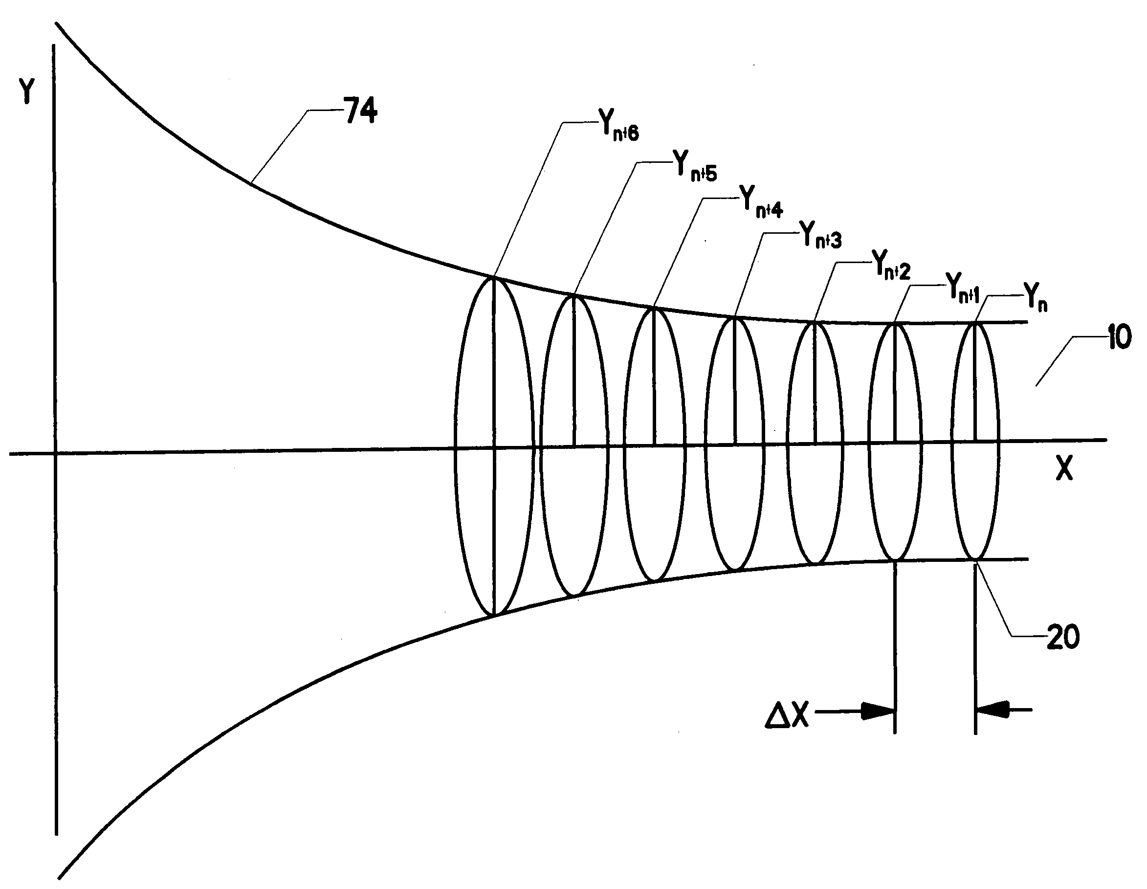
[0062]FIG. 11 graphically depicts one objective of the present invention. Anchor 18 includes an internal passage bounded by an internal surface. The internal surface is created by a revolved profile. Optimized profile 72—represented by the dashed lines in the lower view—is an undefined shape which will create an ideally uniform stress distribution for the potted region. This idealized stress distribution is shown in the upper view of FIG. 11. The optimized profile represents the shape which will most closely approximate the ideal uniform stress distribution. In reality, a completely flat stress curve is not possible. Thus, this diagram represents a goal rather than an expected result.

[0063] Stress within the potted region is a complex phenomenon having many components. FIG. 19 shows analysis element 82 lying at a point within potted region 16. Analysis element 82 is a small portion of the potted region defined to facilitate consideration of stress. The creation of such an element w...


PUM


Abstract

A termination anchor having a neck region, a mid region, and a distal region. An expanding passage through the anchor from the neck region to the distal region is bounded by an internal surface. Exposed strands on a cable are trapped within this expanding passage by infusing them with liquid potting compound (either before or after the strands are placed within the passage). This liquid potting compound solidifies while the strands are within the anchor to form a solidified potted region. The present invention optimizes the profile of the internal surface in order to transfer stress occurring in the neck region to the mid region and the distal region. By transferring some of this stress, a more uniform stress distribution and a lower peak stress are achieved.

Description

BACKGROUND OF THE INVENTION [0001] 1. Field of the Invention [0002] This invention relates to the field of cables and cable terminations. More specifically, the invention comprises a cable termination which redistributes stress in order to enhance the mechanical properties of the termination. 2. Description of the Related Art [0003] Devices for mounting a termination on the end of a wire, rope, or cable are disclosed in detail in copending U.S. Application Ser. No.60 / 404973 to Campbell, which is incorporated herein by reference. [0004] The individual components of a wire rope are generally referred to as “strands,” whereas the individual components of natural-fiber cables or synthetic cables are generally referred to as “fibers.” For purposes of this application, the term “strands” will be used generically to refer to both. [0005] In order to carry a tensile load an appropriate connective device must be added to a cable. A connective device is typically added to an end of the cable,...

Claims


Application Information

Patent Timeline
Patent Type & Authority Applications(United States)
IPC IPC(8): F16G11/00
CPCF16G11/00F16G11/042
Inventor CAMPBELL, RICHARD V.BAREFIELD, KEVIN J.HORTON, JOHN WILEY
Owner BRIGHT TECH CO LTD
Why Eureka
Try Eureka