
Pneumatic run flat tire

a pneumatic run and tire technology, applied in the field of pneumatic run flat tires, can solve the problems of increasing rolling resistance and worsening riding comfort, and achieve the effects of reducing tire weight, optimizing tread profile, and maintaining run-flat durability

Active Publication Date: 2013-08-06
YOKOHAMA RUBBER CO LTD
View PDF3 Cites 4 Cited by
  • Summary
  • Abstract
  • Description
  • Claims
  • Application Information

AI Technical Summary

Benefits of technology

The technology described in this patent addresses issues with traditional pneumatic run flat tires by reducing tire weight while maintaining durability and enhancing riding comfort during regular travel.

Problems solved by technology

However, there are problems with tires having run-flat durability enhanced in this way such as increased rolling resistance caused by increased weight, and worsening of riding comfort when regular traveling caused by increased side stiffness.
However, with both of these proposals, the enhancement of riding comfort when regular traveling and the reduction of tire weight is insufficient, and there is still room for improvement.

Method used


Image

  • Pneumatic run flat tire
  • Pneumatic run flat tire
  • Pneumatic run flat tire

Examples


examples

[0033]Ten types of tires were made for a Conventional Example, Comparative Examples 1 to 4, and Working Examples 1 to 5 with a common tire size of 255 / 40RF19. Shapes of the tire cross-section, and specifications of the bead filler and the reinforcing rubber layer were configured as shown in Table 1.

[0034]The Conventional Example is an example wherein the angle θ and the bead filler height are less, and the reinforcing rubber layer height is greater than the ranges specified in the present technology. Comparative Examples 1 and 2 are examples wherein the bead filler height is outside the range of the present technology. Comparative Example 3 is an example wherein the reinforcing rubber layer height is outside the range of the present technology. Comparative Example 4 is an example wherein the angle θ is outside the range of the present technology.

[0035]Working Examples 1 to 5 are all examples in which the tire cross-sectional shape was within the range specified in the present techno...


PUM

PropertyMeasurementUnit
dynamic elastic modulusaaaaaaaaaa
tan δaaaaaaaaaa
tan δaaaaaaaaaa

Abstract

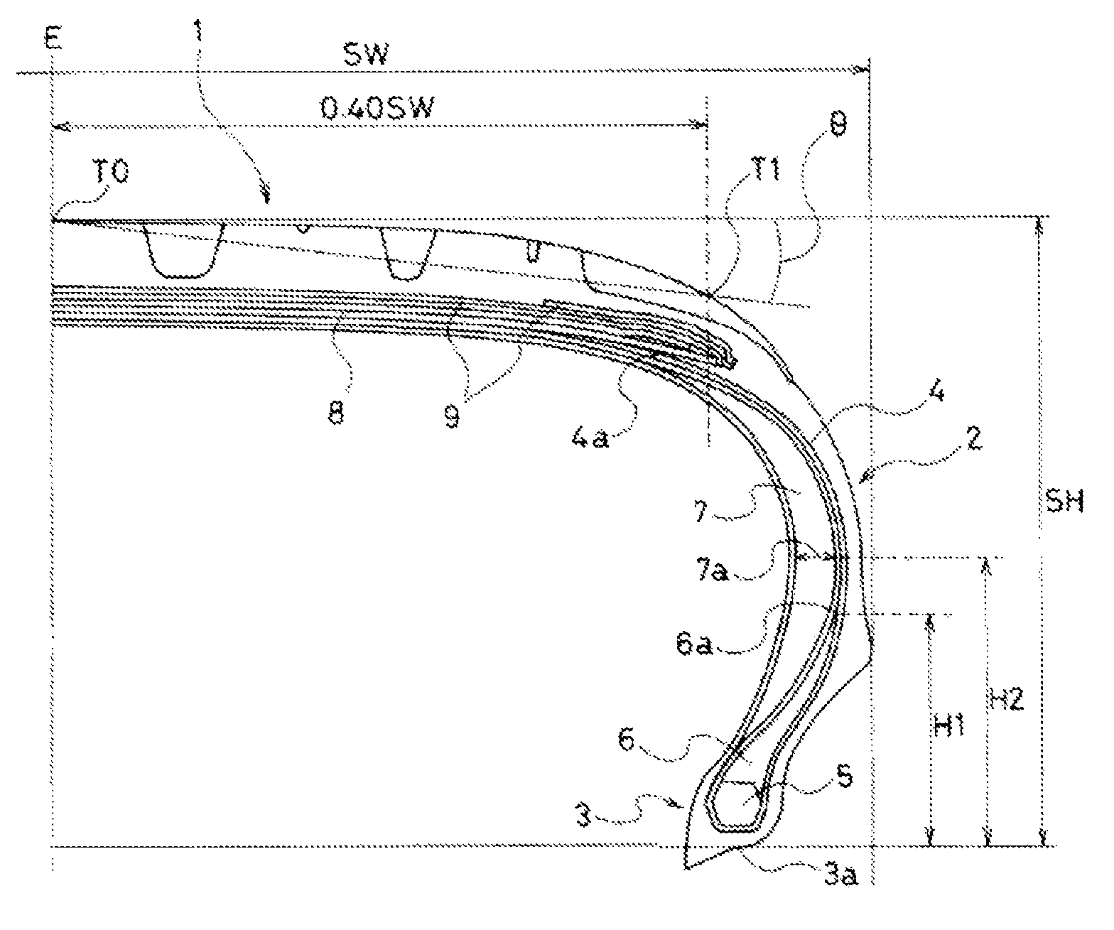
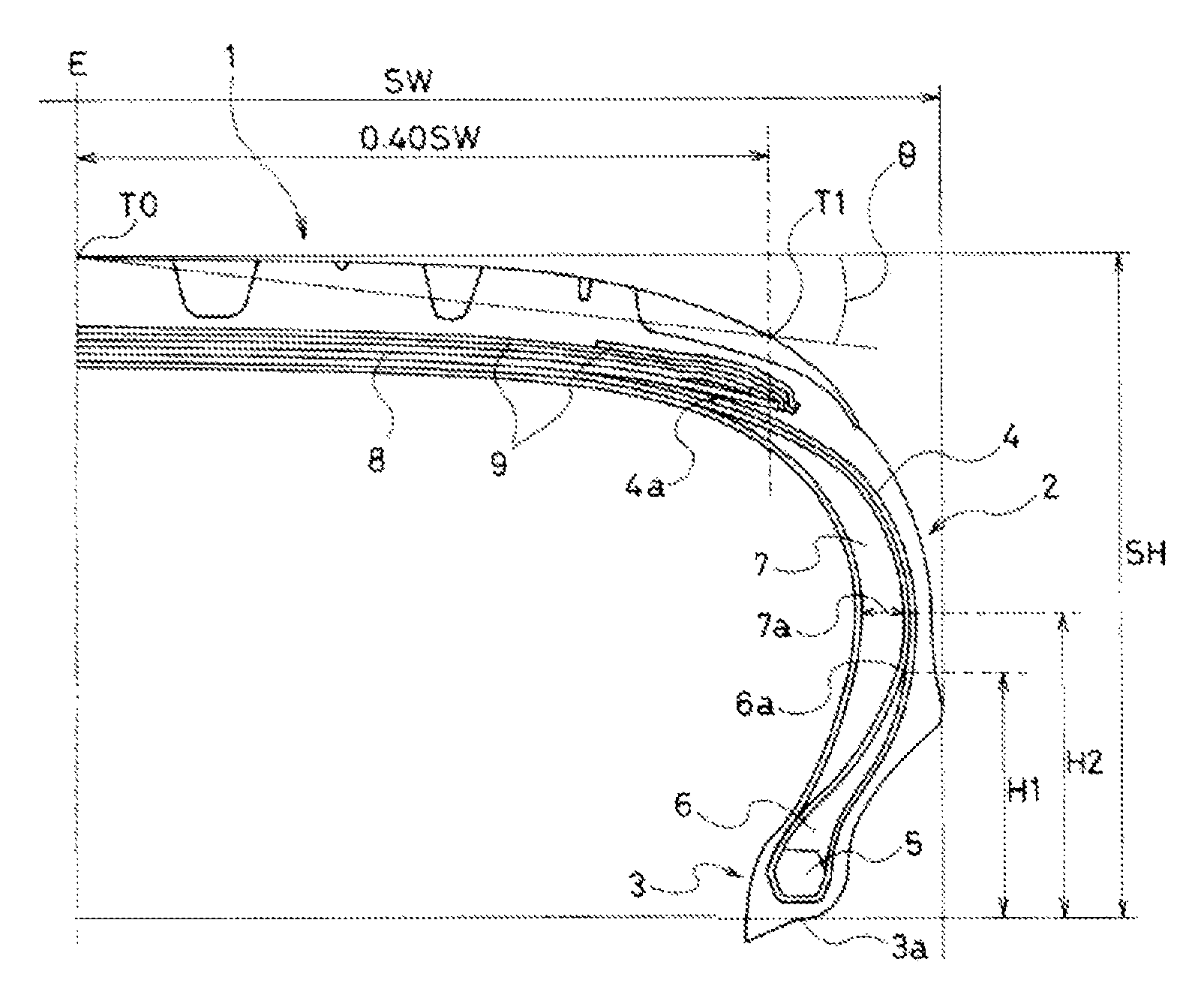
A reinforcing rubber layer having a falcated cross-section disposed on an inner side in a tire width direction of the carcass layer in a side wall portion. An angle θ, with respect to the total tire width SW and a tire cross-section height SH, satisfies a relationship (SH / SW×6+3)°≦θ≦(SH / SW×6+8)°. Additionally, a height H1 of a bead filler is from 15 to 35% of the tire cross-section height SH and a height H2 of a maximum thickness position of the reinforcing rubber layer is from 35 to 55% of the tire cross-section height SH.

Description

PRIORITY CLAIM[0001]Priority is claimed to Japan Patent Application Serial No. 2010-245963 filed on Nov. 2, 2010.BACKGROUND[0002]1. Technical Field[0003]The present technology relates to a pneumatic run flat tire, and particularly Relates to a pneumatic run flat tire in which tire weight can be reduced while maintaining run-flat durability, and which is configured so that riding comfort when regular traveling is enhanced.[0004]2. Related Art[0005]Conventionally, in run flat tires provided with a reinforcing rubber layer having a falcated cross-section on an inner surface side of a side wall portion, methods such as increasing a thickness of the reinforcing rubber layer and using a rubber with a higher hardness for the reinforcing rubber layer have been used in order to ensure durability when run-flat traveling. However, there are problems with tires having run-flat durability enhanced in this way such as increased rolling resistance caused by increased weight, and worsening of ridin...

Claims


Application Information

Patent Timeline
Patent Type & Authority Patents(United States)
IPC IPC(8): B60C17/00B60C3/00B60C15/06
CPCB60C15/0603B60C17/0009B60C3/04Y10T152/10846B60C2017/0063Y10T152/10837
Inventor SHINZAWA, TATSUROU
Owner YOKOHAMA RUBBER CO LTD
Learn More