Pneumatic tire

A technology for pneumatic tires and tires, which is applied to the reinforcement layer of pneumatic tires, tire parts, and no separate inflatable cushions, etc., which can solve the problem of reducing the joint rubber layer of the full joint rubber layer, maintaining air permeability prevention and handling stability, Problems such as the impact on tire manufacturing performance, to achieve the effect of taking into account air permeability, excellent air permeability and handling stability, and good air permeability

Active Publication Date: 2019-07-05
THE YOKOHAMA RUBBER CO LTD
View PDF19 Cites 0 Cited by
  • Summary
  • Abstract
  • Description
  • Claims
  • Application Information

AI Technical Summary

Problems solved by technology

However, with regard to such partial joint rubber layers, each partial joint rubber layer provided in each shoulder region has a pair of ends (an end on the tire equator side and an end on the outer side in the tire width direction), so that the tire component parts The base point of peeling between the tires and / or the number of ends that may become non-crimped portions during manufacture may increase, which may affect the manufacturability of the tire
[0004] On the other hand, if an attempt is made to reduce the amount of the joint rubber layer used by narrowing the width of the conventional full joint rubber layer, it is difficult to obtain a sufficient tire weight reduction effect while maintaining a high level of air permeability prevention and steering stability. properties, it is difficult to balance these performances well, so further improvement is required for the structure and / or arrangement of the partially bonded rubber layer

Method used


Image

  • Pneumatic tire
  • Pneumatic tire
  • Pneumatic tire

Examples


Embodiment

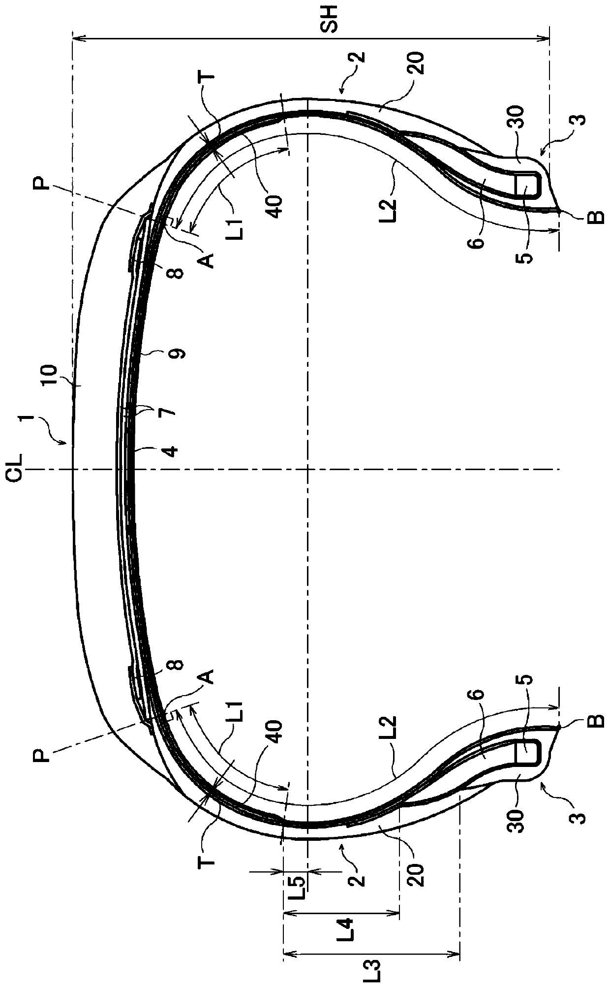
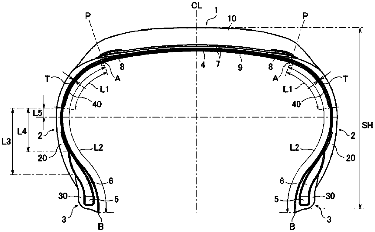
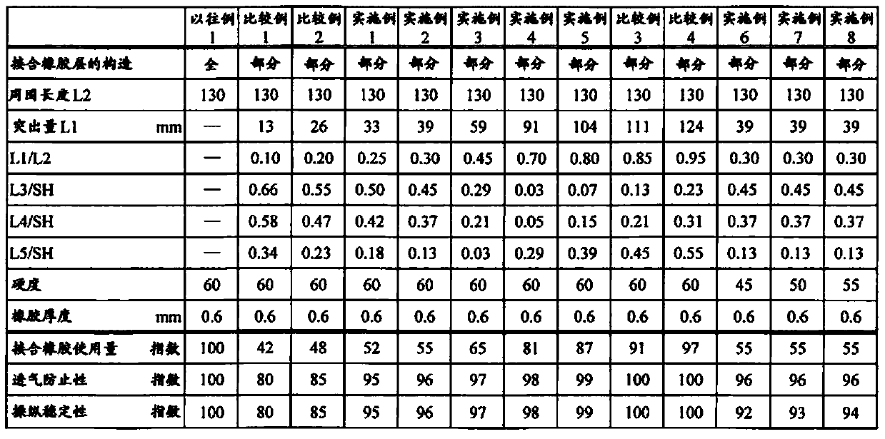
[0033] The tire size is 195 / 65R15, with figure 1 The basic structure shown, and the structure of the joint rubber layer, and the protrusion amount L1 of a part of the joint rubber layer to the bead portion side with respect to the perpendicular line P drawn from the outermost end portion of the belt layer in the tire width direction toward the inner liner , the length L2 around the inner surface of the tire from the intersection point A of the vertical line P and the inner surface of the tire to the head end point B of the bead toe, and the distance between the end of the partially bonded rubber layer and the radially outer end of the rim cushion rubber The ratio of L3 to the tire section height SH (L3 / SH), the ratio of the distance L4 between the end of the partially bonded rubber layer and the tire radially outer end of the bead filler to the tire section height SH (L4 / SH ), the ratio of the distance L5 between the end of the partially bonded rubber layer and the tire maximu...


PUM


Abstract

The present invention relates to a pneumatic tire which comprises a partial tie rubber layer exclusively disposed at a portion between a carcass layer and an inner liner layer, and more specifically provides a pneumatic tire capable of achieving a further reduction in the weight of the tire while maintaining air impermeability and steering stability and achieving an excellent balance between thesecharacteristics. A partial tie rubber layer 40 is disposed between a carcass layer 4 and an inner liner layer 9 and disposed over an area other than the leading end of a bead portion 3. The amount ofprotrusion L1 of the partial tie rubber layer 40 towards the bead portion 3 with respect to a perpendicular line P drawn from the outermost end of a belt layer 7 in the tire width direction to the inner liner layer 9 is set to 0.25 to 0.80 times the peripheral length L2 along the tire inner surface from the intersection A between the perpendicular line P and the tire inner surface to the leadingend point B of a bead toe.

Description

technical field [0001] The present invention relates to a pneumatic tire provided with a partially bonded rubber layer (Japanese: Partial タイゴム layer) that is limitedly arranged between a part of the carcass layer and an inner liner. A pneumatic tire that achieves further reduction in tire weight while handling stability and satisfactorily balances these performances. Background technique [0002] In pneumatic tires, a joint rubber layer is generally disposed between the carcass layer and the inner liner in order to prevent the carcass cord from biting into the inner liner when the unvulcanized tire is inflated during tire manufacture. With regard to such a joint rubber layer, in recent years, in order to achieve a reduction in tire weight and rolling resistance, it is proposed to use not the entire area between the carcass layer and the inner liner but the shoulder areas on the left and right. The selectively arranged part joins the rubber layer (for example, refer to Paten...

Claims


Application Information

Patent Timeline
Patent Type & Authority Applications(China)
IPC IPC(8): B60C5/14B60C13/00
CPCB60C5/14B60C2009/145B60C13/00
Inventor 三好雅章
Owner THE YOKOHAMA RUBBER CO LTD
Why Eureka
Try Eureka