Pneumatic Tire

a technology of pneumatic tires and rims, which is applied in the direction of tire beads, rolling resistance optimization, vehicle components, etc., can solve the problems of deterioration of tire durability due to the omission of bead fillers, and achieve the effects of reducing tire weight, ensuring the durability of the rim fitting portion, and suppressing deterioration of workability of tire mounting

Active Publication Date: 2021-06-10
YOKOHAMA RUBBER CO LTD
View PDF0 Cites 0 Cited by
  • Summary
  • Abstract
  • Description
  • Claims
  • Application Information

AI Technical Summary

Benefits of technology

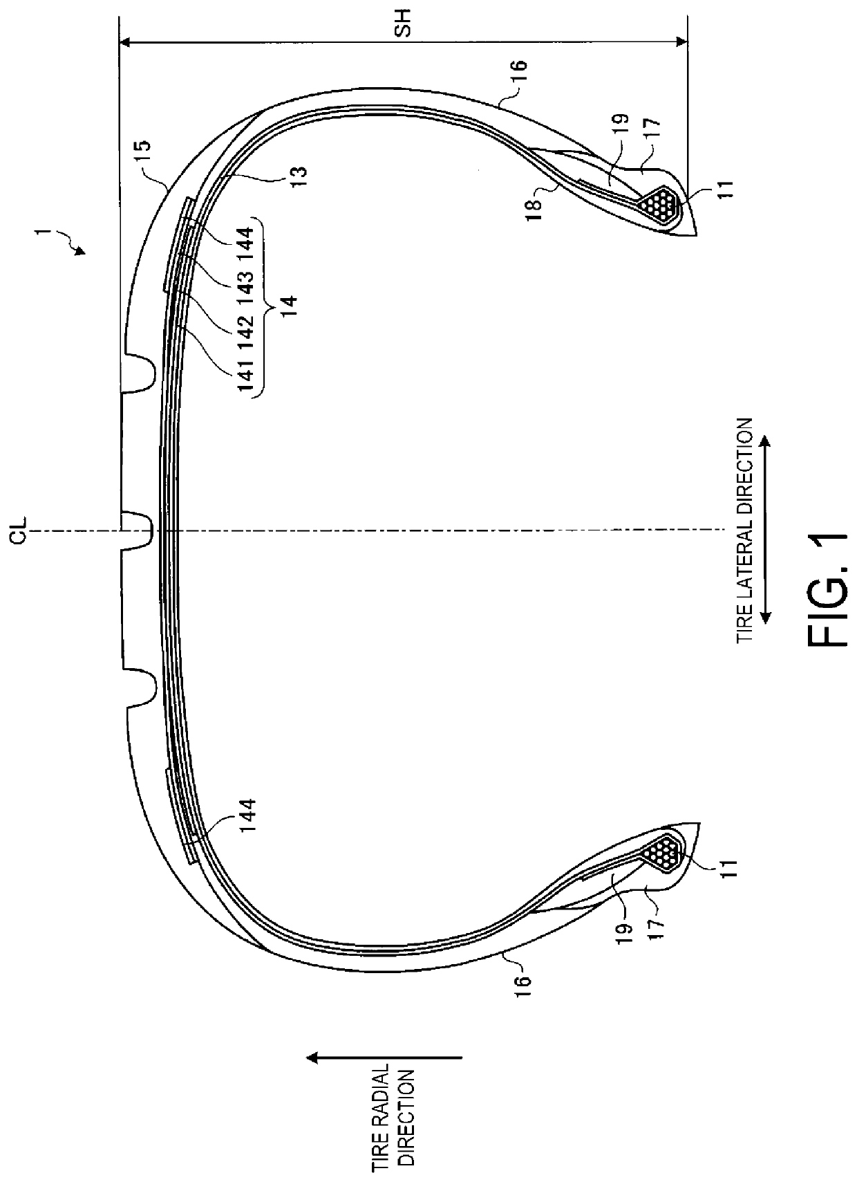
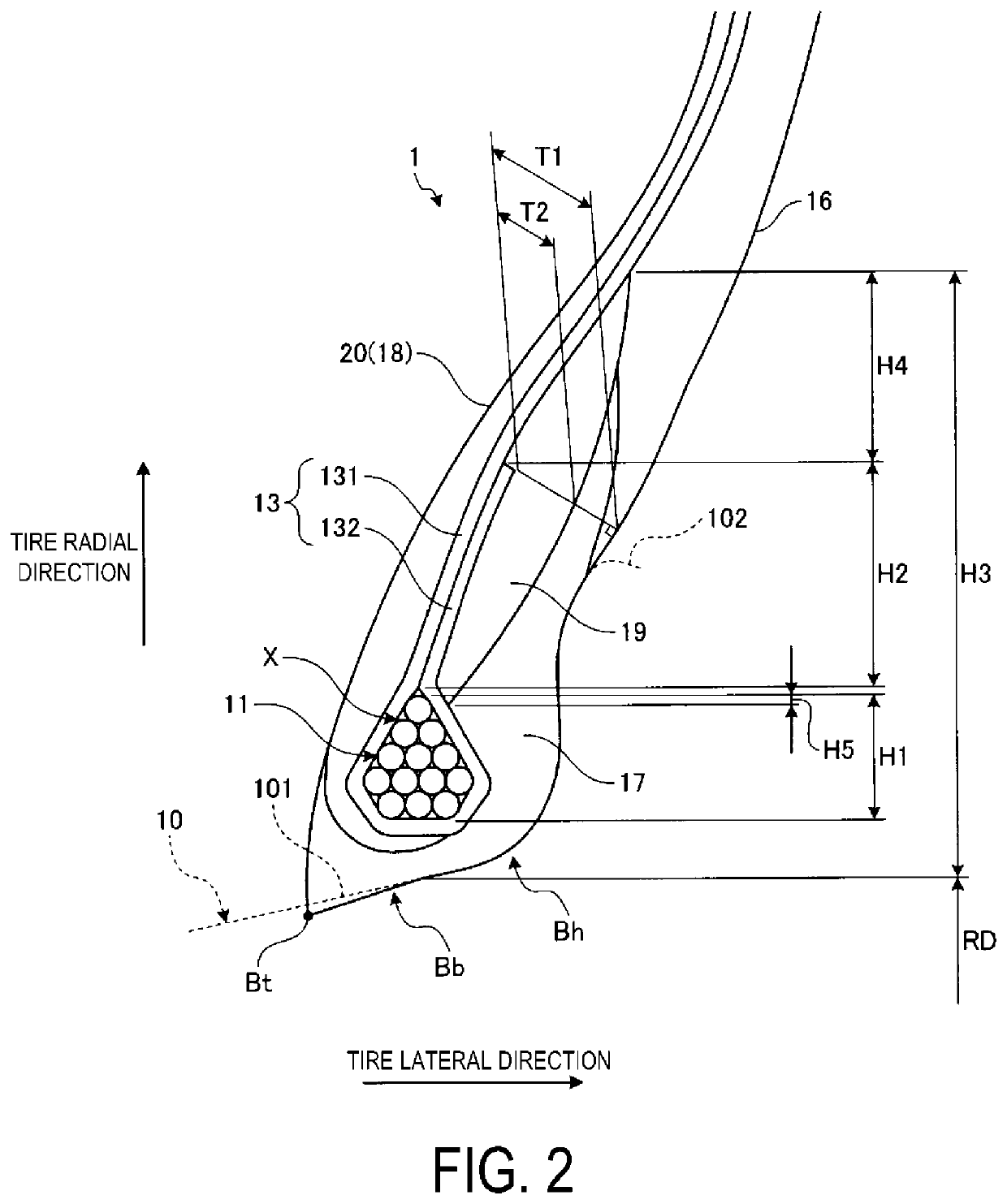
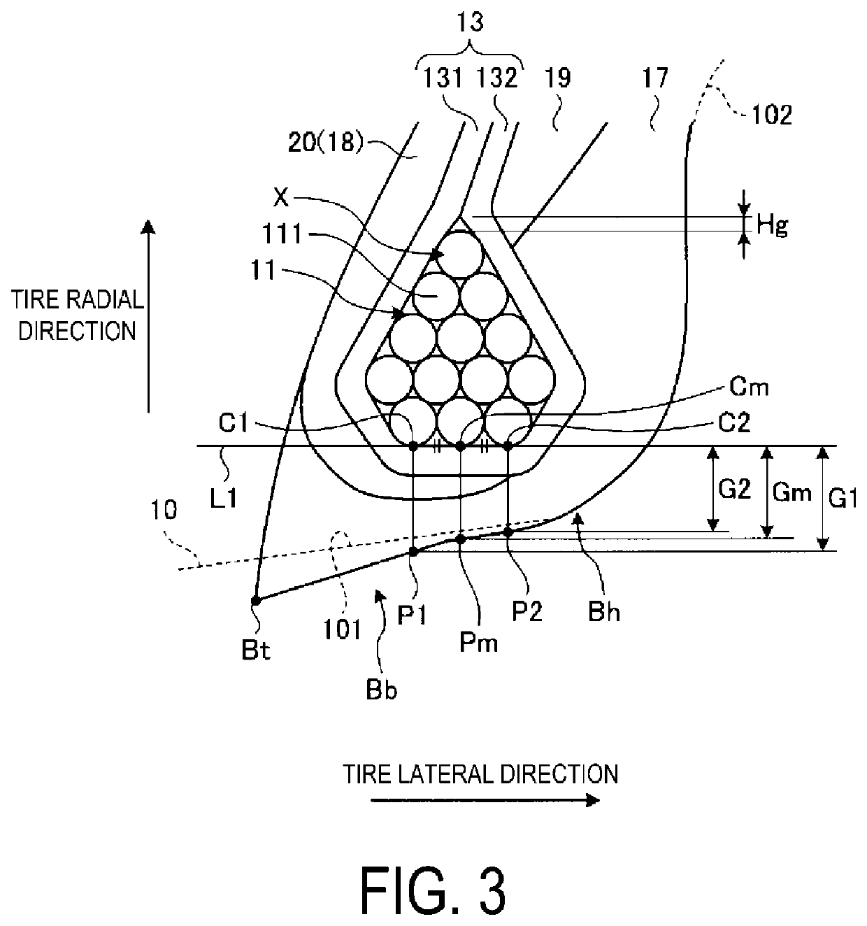
[0139]As described above, the pneumatic tire 1 includes the bead cores 11, the carcass layer 13, and the rim cushion rubber 17. The bead cores 11 are formed by annularly and multiply winding one or a plurality of the bead wires 111. The carcass layer 13 is formed of the carcass ply of a single layer or a plurality of layers. The carcass layer 13 is turned back so as to wrap the bead cores 11 and extended between the bead cores 11. The rim cushion rubber 17 is disposed along the turned back portion 132 of the carcass layer 13 to constitute the rim fitting surface of the bead portion (see FIGS. 1 and 2). The turned back portion 132 of the carcass layer 13 contacts the body portion 131 of the carcass layer 13 in the cross-sectional view in the tire meridian direction to form the closed region X surrounding the bead cores 11 (see FIG. 2). The rubber occupancy ratio in the closed region X is in the range of 15% or less. The bead cores 11 have the predetermined wire arrangement structure formed by arranging the wire cross sections of the bead wires 111 in the cross-sectional view in the tire meridian direction (see FIG. 4). The tangent line L1 that contacts the innermost layer in the tire radial direction and the wire cross sections innermost and outermost in the tire lateral direction in the wire arrangement structure from the rim fitting surface side, and the contact point C2 of the tangent line L1 on the wire cross section on the outermost are defined (see FIG. 6). At this time, the gauge Wh in the tire lateral direction from the contact point C2 to the rim fitting surface and the outer diameter φ of the bead wire have a relationship 2.0≤Wh / φ≤15.0. Additionally, the radial height H2 of the contact portion between the body portion 131 and the turned back portion 132 of the carcass layer 13 has the relationship 0.80≤H2 / H1≤3.00 to the radial height H1 of the bead cores 11.
[0140]In such a configuration, (1) the rubber occupancy ratio in the closed region X surrounded by the body portion 131 and the turned back portion 132 of the carcass layer 13, that is, the rubber volume around the bead cores 11, is set to be considerably low. Thus, since bead fillers can be omitted, the weight of the tire can be reduced. Thus, (2) the ratio Wh / φ brings an advantage that the gauge Wh of the rim fitting portion is made appropriate. That is, the lower limit ensures the gauge Wh of the rim fitting portion and ensures the durability of the rim fitting portion. Additionally, the upper limit suppresses deterioration of workability of mounting of the tire on the rim due to the excessive gauge Wh of the rim fitting pressure. Additionally, (3) the range of H2 / H1 brings an advantage that the radial height H2 of the self-contact portion of the carcass layer 13 is made appropriate. In other words, the lower limit causes the turned back portion 132 to be stably supported to the body portion 131, thus improving durability of the bead portion. In addition, the upper limit suppresses an increase in tire weight due to the excessive amount of the turned back portion 132.
[0141]Additionally, in the pneumatic tire 1, a layer in which the number of arrangements of the wire cross sections is the maximum in the wire arrangement structure (in FIG. 4, the second layer from the innermost layer) is defined as the maximum arrangement layer. At this time, the number of layers of the wire cross sections outward in the tire radial direction with respect to the maximum arrangement layer (three layers in FIG. 4) is greater than the number of layers of the wire cross sections inward in the tire radial direction with respect to the maximum arrangement layer (one layer in FIG. 4). Additionally, the number of arrangements of the wire cross sections in each layer outward in the tire radial direction with respect to the maximum arrangement layer monotonically decreases outward in the tire radial direction from the maximum arrangement layer (see FIG. 4). This has an advantage that a gap between the joining portion of the body portion 131 with the turned back portion 132 of the carcass layer 13 and the top portion (so-called bead top) outward of the bead core 11 in the tire radial direction becomes small, and the durability of the bead portion is improved. In particular, the structure in which bead fillers are omitted described above is preferred in that the rubber occupancy ratio in the closed region X can be reduced. In addition, there is an advantage that, since the turned back portion 132 can bend at an obtuse angle at the joining position with the body portion 131, the amount of bending of the turned back portion 132 becomes small, and the durability of the bead portion is improved.
[0142]Additionally, in the pneumatic tire 1, the arrangement angle θ2 of the wire cross sections at the corner portion inward in the tire radial direction and outward in the tire lateral direction of the wire arrangement structure is in the range 80 degrees≤θ2 (see FIG. 4). This has an advantage that disruption of the wire arrangement structure during tire vulcanization is suppressed, and the durability of the bead portion is improved.
[0143]Additionally, in the pneumatic tire 1, the arrangement angle θ2 of the wire cross sections at the corner portion inward in the tire radial direction and outward in the tire lateral direction of the wire arrangement structure is in the range 100 degrees≤θ2≤150 degrees (see FIG. 4). This has an advantage that disruption of the wire arrangement structure during tire vulcanization is suppressed, and the durability of the bead portion is improved.
[0144]Additionally, in the pneumatic tire 1, the actual length La2 of the contact portion between the body portion 131 and the turned back portion 132 of the carcass layer 13 has the relationship 0.30≤La2 / La1≤2.00 with respect to the circumferential length La1 of the closed region. Thus, the actual length La2 of the self-contact portion of the carcass layer 13 is made appropriate. That is, the lower limit properly ensures spring characteristics of the carcass layer 13 and ensures the durability of the bead portion. In addition, the upper limit suppresses an increase in tire weight due to the excessive amount of the turned back portion 132.

Problems solved by technology

However, in the conventional pneumatic tire described above, deterioration of durability of the tire due to the omission of the bead fillers is a concern.

Method used


Image

  • Pneumatic Tire
  • Pneumatic Tire
  • Pneumatic Tire

Examples


example

[0153]FIG. 14 is a table showing results of performance tests of pneumatic tires according to the embodiment of the technology. FIG. 15 is an explanatory diagram illustrating bead cores of a test tire of Conventional Example.

[0154]In the performance test, a plurality of types of test tires having a tire size of 205 / 55R16 were evaluated for (1) tire mass and (2) durability.

[0155](1) The tire mass is calculated as the average value of the masses of five test tires having the same structure. The measurement results are expressed as index values and evaluated with the Conventional Example being assigned as the reference (100). The smaller the values in this evaluation, the lighter the test tires are, which is preferred. Additionally, when the index is 99 or less, it can be said that the weight of the tire is reduced compared to that of the existing tire structure including bead fillers.

[0156](2) In the evaluation for durability, the test tires are mounted on rims having a rim size of 16...


PUM


Abstract

In a pneumatic tire, bead cores have a wire arrangement. In a cross-sectional view in a tire meridian direction, a tangential line and a contact point are defined. The tangential line contacts an innermost layer in a radial direction and the wire cross sections innermost and outermost in a lateral direction in the wire arrangement from a rim fitting surface side. The contact point of the tangent line is on the wire cross section on the outermost side. A gauge Wh in the lateral direction from the contact point to the rim fitting surface and an outer diameter φ of the bead wire have a relationship 2.0≤Wh/φ≤15.0. A radial height H2 of a contact portion between a body portion and a turned back portion of a carcass layer has a relationship 0.80≤H2/H1≤3.00 to a radial height H1 of the bead cores.

Description

TECHNICAL FIELD[0001]The technology relates to a pneumatic tire and particularly relates to a pneumatic tire that can improve durability of the tire while a weight of the tire is reduced.BACKGROUND ART[0002]In recent years, for weight reduction of a tire, weight reduction of bead portions has been advanced. As a conventional pneumatic tire, a technology described in Japan Unexamined Patent Publication No. 2008-149778 has been known. In Japan Unexamined Patent Publication No. 2008-149778, bead fillers are omitted to reduce a weight of the tire.[0003]However, in the conventional pneumatic tire described above, deterioration of durability of the tire due to the omission of the bead fillers is a concern.SUMMARY[0004]The technology provides a pneumatic tire that can improve durability of the tire while a weight of the tire is reduced.[0005]A pneumatic tire according to an embodiment of the technology includes bead cores, a carcass layer, and a rim cushion rubber. The bead cores are forme...

Claims


Application Information

Patent Timeline
Patent Type & Authority Applications(United States)
IPC IPC(8): B60C15/04B60C15/06B60C15/00
CPCB60C15/04B60C15/0628B60C15/0009B60C2015/009B60C2015/048B60C2015/0678B60C2015/046B60C2015/0621B60C15/0027B60C15/0054Y02T10/86B60C2015/0614
Inventor TANNO, ATSUSHIKODA, HIRAKUMATSUDA, JUN
Owner YOKOHAMA RUBBER CO LTD
Why Eureka
Try Eureka