Pneumatic Tire

a pneumatic tire and tire body technology, applied in the field of pneumatic tires, can solve the problems of preventing affecting the manufacturability of tires, and difficult to maintain air permeation, so as to reduce tire weight, prevent performance and steering stability, and reduce tire weight. the effect of sufficient weigh

Pending Publication Date: 2019-11-21
YOKOHAMA RUBBER CO LTD
View PDF3 Cites 0 Cited by
  • Summary
  • Abstract
  • Description
  • Claims
  • Application Information

AI Technical Summary

Benefits of technology

[0007]As compared to the related-art pneumatic tire having a full tie rubber layer, when reducing tire weight by employing the partial tie rubber layer in the present technology, the protruding amount L1 with respect to the perpendicular line P (that is, the position of the outermost end portion of the belt layer in the tire lateral direction) is set as described above. Thus, a minimum region necessary for achieving air permeation preventing performance and steering stability comparable to those in the related art can be covered by the partial tie rubber layer while reducing tire weight sufficiently, and it is possible to maintain excellent air permeation preventing performance and steering stability at a known level. As a result, air permeation preventing performance, steering stability, and reduction in tire weight can be achieved in a well-balanced manner. Note that, in the present technology, “periphery length” refers to a length measured along the extension direction of each tire component (partial tie rubber layer) in the tire meridian cross-section.
[0008]In the present technology, it is preferred that the protruding amount L1 of the partial tie rubber layer be equal to or larger than 15 mm. By setting the protruding amount L1 to the appropriate range and performing optimization in this manner, air permeation preventing performance, steering stability, and reduction in tire weight can be achieved in a further balanced manner.
[0009]In the present technology, it is preferred that hardness of the rubber constituting the partial tie rubber layer be from 50 to 70. With this, it is possible to compensate for the rigidity of the sidewall portions that may be degraded along with the suppression of the usage amount of the partial tie rubber layer, which is advantageous in maintaining steering stability. Note that the term “rubber hardness” in the present technology is construed under JIS (Japanese Industrial Standard) K6253, and is measured by a type A durometer at a temperature of 20° C. (so-called JIS-A hardness).
[0010]In the present technology, it is preferred that a thickness of the partial tie rubber layer be from 0.1 mm to 1.0 mm. By setting the thickness of the partial tie rubber layer to the appropriate range and performing optimization in this manner, air permeation preventing performance, steering stability, and reduction in tire weight can be achieved in a further balanced manner. Note that the term “thickness of the partial tie rubber layer” is the thickness of the main portion of the partial tie rubber layer (portion that extends while maintaining a constant thickness). When the partial tie rubber layer has a tapered shape in which the thickness decreases toward the end portion, for example, the thickness of the partial tie rubber layer is the thickness of the portion except for the end portion.

Problems solved by technology

This may affect manufacturability of the tire.
Meanwhile, when attempting to reduce the usage amount of the tie rubber layer by narrowing the width of the related-art full tie rubber layer, it is difficult to maintain air permeation preventing performance and steering stability at a high level while achieving sufficient tire weight reduction effect thereby achieving such performance in a balanced manner.

Method used


Image

  • Pneumatic Tire

Examples


examples

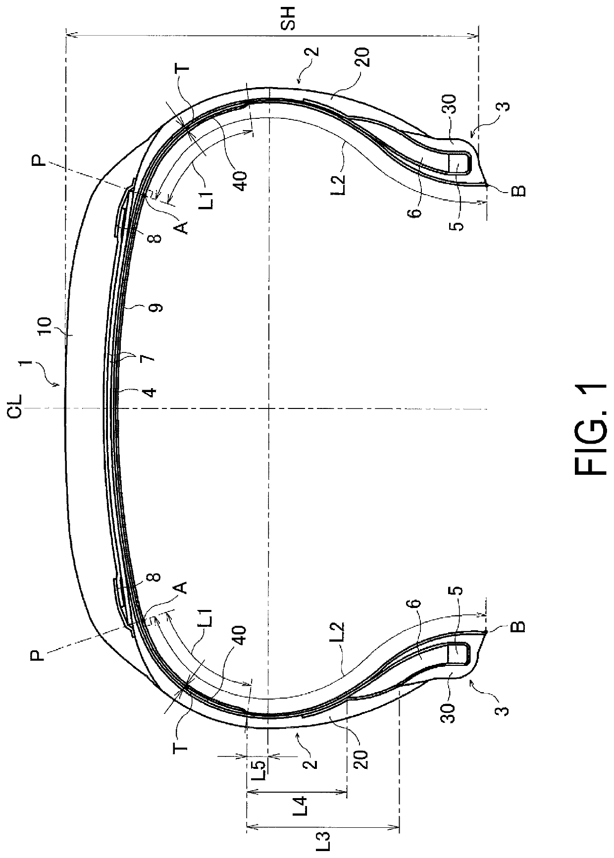
[0025]25 types of pneumatic tires including Conventional Example 1, Comparative Examples 1 to 4, and Examples 1 to 20 were manufactured. Each of the tires had a tire size of 195 / 65R15 and a basic structure illustrated in FIG. 1, and was set to have the following conditions as shown in Table 1 or 2: a structure of a tie rubber layer; a protruding amount L1 of the partial tie rubber layer toward a bead portion with respect to a perpendicular line P, which is drawn from an outermost end portion of the belt layer in the tire lateral direction toward an innerliner layer; a periphery length L2 along a tire inner surface from an intersection point A of the perpendicular line P and a tire inner surface to a tip point B of a bead toe; a ratio of a separation distance L3 between the end portion of the partial tie rubber layer and an end portion of a rim cushion rubber layer on an outer side in the tire radial direction with respect to a tire cross-sectional height SH (L3 / SH); a ratio of a sep...


PUM


Abstract

Provided is a pneumatic tire having a partial tie rubber layer disposed between a carcass layer and an innerliner layer in all region except for tips of bead portions. A protruding amount of the partial tie rubber layer toward the bead portion with respect to a perpendicular line, which is drawn from an outermost end portion of a belt layer in a tire lateral direction toward the innerliner layer, is 0.25 times to 0.80 times as large as a periphery length along a tire inner surface from an intersection point of the perpendicular line and the tire inner surface to a tip point of a bead toe.

Description

TECHNICAL FIELD[0001]The present technology relates to a pneumatic tire provided with a partial tie rubber layer limitedly disposed between a portion between a carcass layer and an innerliner layer, and particularly relates to a pneumatic tire that achieves further reduction in tire weight while maintaining air permeation preventing performance and steering stability in a well-balanced manner.BACKGROUND ART[0002]In a pneumatic tire, a tie rubber layer is disposed between a carcass layer and an innerliner layer in order to prevent carcass cords from biting into the innerliner layer when an unvulcanized tire is inflated at the time of manufacturing the tire. In recent years, in order to reduce tire weight and rolling resistance, with regard to such tie rubber layer, it has been proposed to employ a partial tie rubber layer that is selectively disposed in right and left shoulder regions instead of all the region between the carcass layer and the innerliner layer (for example, see Japan...

Claims


Application Information

Patent Timeline
Patent Type & Authority Applications(United States)
IPC IPC(8): B60C5/14
CPCB60C5/14B60C2009/145B60C13/00
Inventor MIYOSHI, MASAAKI
Owner YOKOHAMA RUBBER CO LTD
Why Eureka
Try Eureka