Charging system for electric vehicles

a charging system and electric vehicle technology, applied in the direction of charging stations, electric devices, transportation and packaging, etc., can solve the problems of limited power available for charging rarely using the option to specify the desired amount of energy, and the inability to charge a further electric vehicle at a charging station, etc., to achieve the effect of optimizing the operation of the charging station, increasing the user's friendliness, and improving the efficiency of the charging station

Pending Publication Date: 2021-09-02
COMPLEO CHARGING SOLUTIONS AG
View PDF0 Cites 4 Cited by
  • Summary
  • Abstract
  • Description
  • Claims
  • Application Information

AI Technical Summary

Benefits of technology

[0015]Therefore, the object of the application is to provide a charging system for charging electric vehicles that optimizes the operation of the charging stations, in particular, the efficiency of the charging stations, and at the same time increases the user friendliness.
[0021]In contrast to the prior art, according to the application, a charging system with a plurality of charging stations is provided, which optimizes the operation of the charging stations, in particular, the efficiency of the charging stations, and at the same time increases the user friendliness by basing the determination of the charging curve profile on historical, in particular, user-specific and charging position-specific, charging process data sets. The charging power to be reserved by a charging curve profile can be optimized. User inputs via a user interface module can be omitted.
[0058]Preferably, other available user data may alternatively or additionally be considered by the charging profile determination module, such as working time data of the user. In particular, user-specific data (which can be stored in a user account) can include a user group of the user. For example, it is conceivable that such a user group is assigned to a specific shift work. Advantageously, this makes it possible to estimate the departure time of a user and thus the charging process duration with an increased probability and accuracy, respectively. Example: a user is a worker and wants to charge his electric vehicle during his working hours. For example, the shift work of the worker extends from 6:00 am to 2:00 pm. Thus, the worker may belong to the “early shift” user group, for example. It is very unlikely that the worker will already drive home with his electric vehicle at 10:00 am. The predicted time at which the charging process must be successfully completed, i.e. the estimated charging process time duration, is approximately 2:00 pm in the example. Such information can be used in determining a charging curve profile.
[0064]Advantageously, by using the charging curve intervals and, in particular, the possible adaptation of the charging curve profile, an optimal utilization can be achieved. Advantageously, the use of charging curve intervals can limit the degree of complexity of the control module, since in one embodiment (always) only a part (the period of a few load curve intervals) of the load curve profile can be calculated.
[0066]Example: If, based on user-specific data, it is determined by a computer-aided evaluation (e.g., by the charging profile determination module) that a user would like to use the electric vehicle to be charged with a very high probability at 3:00 pm and at 2:00 pm the current state of charge of the electric vehicle (and battery, respectively) is not yet sufficient for a desired mobility, then the charging curve profile of the charging process, in particular, the charging power, can be changed between 2:00 pm and 3:00 pm in such a way that the desired mobility can be ensured at 3:00 μm. The user thus receives a high dynamic prioritization value at 2:00 pm in the example, which can result in that in the course of the charging curve profile determination according to the application a high proportion of the maximum available power is supplied to the electric vehicle of the user at the charging station.

Problems solved by technology

Furthermore, it can be seen that no power can be made available for a further charging point of the charging station (or a further neighboring charging station) at least between time point t1 and time point t2.
This can result in that the power available for charging a further electric vehicle at a charging station is limited during specific periods.
In practice, however, it has been shown in the operation of known charging systems that users rarely use the option to specify the desired amount of energy and / or the desired charging duration and charging process time duration, respectively, using the user interface.
One reason for this is that entering the information results in increased effort for the user.

Method used


Image

  • Charging system for electric vehicles
  • Charging system for electric vehicles
  • Charging system for electric vehicles

Examples


Embodiment Construction

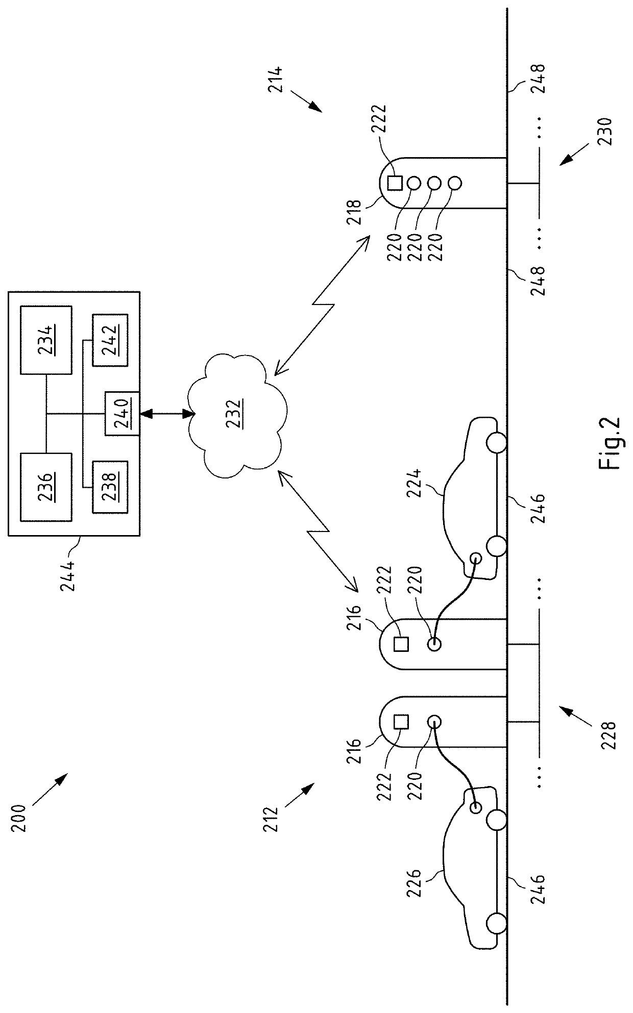
[0080]FIG. 2 shows a schematic view of an embodiment of a charging system 200 according to the present application. The charging system 200 comprises a plurality of charging stations 216, 218 and at least one charging profile determination module 234, for example, in the form of a control module, such as a neural network or a control model based on a machine learning algorithm.

[0081]In the present example, in particular, two charging stations 216 each having one charging point 220 are grouped into a charging (station) arrangement 212. The charging arrangement 212 and the charging stations 216 of the charging arrangement 212, respectively, are connected to a first supply power grid 228, for example, a first local power grid 228, and are located at a first location.

[0082]Further, by way of example, a further charging station 218 having three charging points 220 is arranged. In the present embodiment, the charging station 218 is connected to a further supply power grid 230, for example...


PUM


Abstract

A charging system for electric vehicles that includes a plurality of charging stations each adapted to exchange electrical power with at least one electric vehicle. At least one charging profile determination module adapted to: obtain a charging station identifier associated with a first charging station of the plurality of charging stations and a user identifier associated with a user of an electric vehicle to be charged at the first charging station during a charging process. Determining based on the obtained user identifier and the obtained charging station identifier, at least one historical charging process data set relating to the user identifier and the charging station identifier. Estimating at least one charging parameter for the charging process based on the at least one historical charging process data set, and determining the charging curve profile for the charging process based on at least the at least one estimated charging parameter.

Description

CROSS-REFERENCE TO RELATED PATENT APPLICATIONS[0001]This patent application is a continuation of International Application No. PCT / EP2019 / 081491, filed on Nov. 15, 2019, which claims the benefit of priority to German Patent Application No. 10 2018 129 355.6, filed Nov. 21, 2018, the entire teachings and disclosures of both applications are incorporated herein by reference thereto.FIELD OF INVENTION[0002]The application relates to a charging system for electric vehicles, comprising a plurality of charging stations, each configured to exchange electrical power with at least one electric vehicle. In addition, the application relates to a method for operating a charging system.BACKGROUND[0003]Charging systems for charging electric vehicles are known from the prior art. Known charging systems comprise one or more charging station(s), which may be communicatively coupled to a backend system. A charging station may comprise at least one charging point to which an electric vehicle to be cha...

Claims


Application Information

Patent Timeline
Patent Type & Authority Applications(United States)
IPC IPC(8): B60L53/67B60L53/65
CPCB60L53/67B60L2260/44B60L2250/20B60L53/65B60L53/62B60L53/63B60L2260/54B60L53/665B60L2260/52B60L2260/58B60L2260/46B60L2260/48B60L2240/72Y02T10/72Y02T90/167Y02T90/16Y02T10/70Y02T10/7072Y02T90/12Y04S30/14Y04S10/126Y02E60/00B60L3/12
Inventor CATER, STEPHAN
Owner COMPLEO CHARGING SOLUTIONS AG
Why Eureka
Try Eureka