Base station device

a base station and device technology, applied in lighting and heating equipment, electrical equipment, cooling/ventilation/heating modifications, etc., can solve the problems of increasing the weight and size of the base station body, requiring a large amount of running cost becomes significant, and achieves the effect of reducing the introductory cos

Inactive Publication Date: 2005-09-22
PANASONIC CORP
View PDF14 Cites 6 Cited by
  • Summary
  • Abstract
  • Description
  • Claims
  • Application Information

AI Technical Summary

Benefits of technology

[0019] It is a first object of the present invention to provide a base station enabling itself to be installed in a desired installation position readily and promptly, and further enabling great reduction in introductory cost.

Problems solved by technology

Therefore, in order to expand a communication area by installing such a large-scale base station in a blind zone, a great deal of introductory cost and running cost is required.
However, in the case of expanding a communication area by installing the conventional large-scale base station in a blind zone such as a mountainous area having a small number of subscribers as compared with urban areas having a large number of subscribes, since a possibility is high that a high use rate is not expected unlike urban areas, reduction in introductory cost and running cost becomes significant issues.
However, in such a conventional type of base station, for example, even in the case of constituting an extremely small-size and small-capacity base station using a single BB (Base Band signal processor) board with several ten channels, the weight and size of the base station body become significantly great.
Therefore, even when a communication area is expanded using such a small-capacity base station, construction for installation requires machinery and materials to some extent and several operators.
In particular, when a base station is placed in a mountainous area such that a construction vehicle cannot reach a target place, it is necessary to carry machinery and materials for installation and a base station body by hands, thereby requiring more manpower and time.
Accordingly, in the case of expanding a communication area using a conventional small-capacity base station that is merely miniaturized, a risk is high of not sufficiently expecting decreases in introductory cost and easy and prompt expansion of communication area.
Meanwhile, this type of base station often causes an initial failure at the time of installation.
A delay in service of communication channels due to such a failure becomes a cause of delaying a setup of the entire communication system and creating great disadvantages.
However, such construction for exchanging base stations is operation for removing the base station with the failure occurring, and then installing a base station for exchange.
Therefore, such exchange construction requires effort and time almost twice more than that in new construction for newly installing a base station.
As described above, this type of conventional base station requires enormous cost and effort for the installation.
Therefore, in the conventional motherboard, when the printed-circuit boards are attached to the external container in such a state that the motherboard connectors are connected to the respective printed-circuit board connectors of the plurality of printed-circuit boards, large stress is imposed on the printed-circuit boards due to errors in placement positions between the motherboard connectors and printed-circuit board connectors, and there arises a risk that the printed-circuit boards tend to cause a failure due to the stress.

Method used


Image

  • Base station device
  • Base station device
  • Base station device

Examples


Embodiment Construction

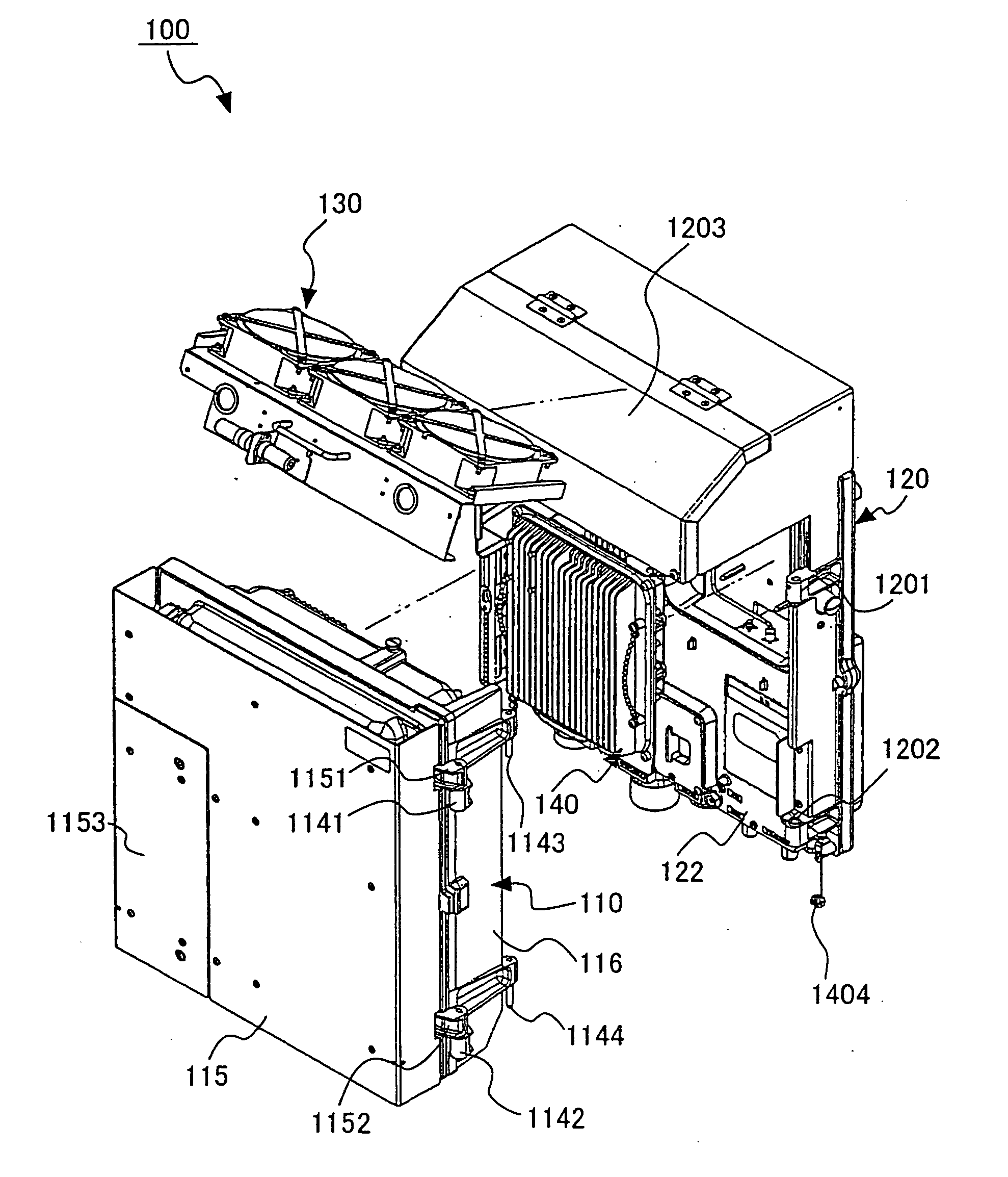
[0053] A base station of the present invention adopts a configuration where an external container is divided into a first flat-type external container that is fixed to an installation place and a second flat-type external container that holds circuit boards and that is detachably attached to the first external container, and the second external container is disposed on the outside of the first external container with heat dissipation space provided therebetween.

[0054] By this means, in this base station, since the external container is divided, each part of the external container becomes small in size and the operability is improved. Further, in this base station, since the second external container is disposed on the outside of the first external container with heat dissipation space provided therebetween, the heat dissipation characteristics are extremely improved. Furthermore, in this base station, since the heat dissipation characteristics of each external container is improved...


PUM


Abstract

An external container is divided into IF unit 120 as a first flat-type external container that holds T-PA unit 140 provided with transmission power amplifier T-PA which amplifies transmission and reception signals and that is fixed to an installation place, and MDE unit 110 as a second flat-type external container that holds a circuit board of modulation and demodulation equipment (MDE) which modulates and demodulates transmission and reception signals and that is detachably attached to the first external container, MDE unit 110 is disposed on the outside of IF unit 120 with heat dissipation space provided therebetween, and a fin as a radiating member is provided on each of opposite faces of IF unit 120 and MDE unit 110.

Description

TECHNICAL FIELD [0001] The present invention relates to a base station in a communication system, and more particularly, to a base station suitable for use as a radio base transceiver station in a 3rd generation mobile communication system. [0002] Further, the present invention relates to a motherboard on which is provided a plurality of motherboard connectors connected to respective printed-circuit board connectors provided on a plurality of printed-circuit boards, and more particularly, to a motherboard and a base station suitable for use in a radio base transceiver station in a communication system. BACKGROUND ART [0003] In recent years, with rapid increases in cellular telephone subscriber, prompt expansion has been required of a communication area of a mobile communication system capable of supporting demand for not only speech communications but also other service such as data, music and image. As is well known, expansion of a communication area of the mobile communication sys...

Claims


Application Information

Patent Timeline
Patent Type & Authority Applications(United States)
IPC IPC(8): H04B1/036H05K7/20
CPCH04B1/036
Inventor EGAWA, MANABU
Owner PANASONIC CORP
Why Eureka
Try Eureka