Pedal apparatus

A technology of pedals and accelerator pedals, applied in the direction of mechanical control devices, foot-operated starting devices, braking action starting devices, etc., can solve the problems of compressing the driver, hindering getting on and off the car, increasing danger, etc., and achieve smooth brakes and accelerators The effect of improving the reliability of the operation and braking and reducing the introduction cost

Inactive Publication Date: 2019-10-11
常深和生
View PDF8 Cites 5 Cited by
  • Summary
  • Abstract
  • Description
  • Claims
  • Application Information

AI Technical Summary

Problems solved by technology

[0010] Furthermore, the prior art must employ complex and bulky mechanisms
In the structure of prior art 1, there is a complicated accelerator mechanism consisting of an accelerator wire arm, an accelerator lever, and an accelerator pedal pad on the right side of the brake pedal. In the case of emergency braking, in the case of mistakenly stepping on these accelerator mechanisms due to the foot that is stepping on the brake pedal slightly shifted to the right, the brakes may not be sufficiently applied, which can also cause a malfunction
On the other hand, in the structure of prior art 2, since the accelerator pedal liner itself is set to be rotatable, the volume of the brake pedal itself becomes larger.
Large pedals compress the space under the driver's feet, which not only hinders getting on and off the vehicle, but also impairs the operability or operating feeling of the pedals due to the size of the inertial weight. In addition, objects that fall on the ground are caught underneath and hinder brake operation. the risk will also increase

Method used


Image

  • Pedal apparatus
  • Pedal apparatus
  • Pedal apparatus

Examples


Embodiment Construction

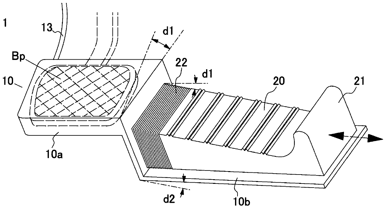
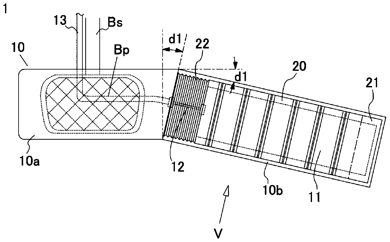
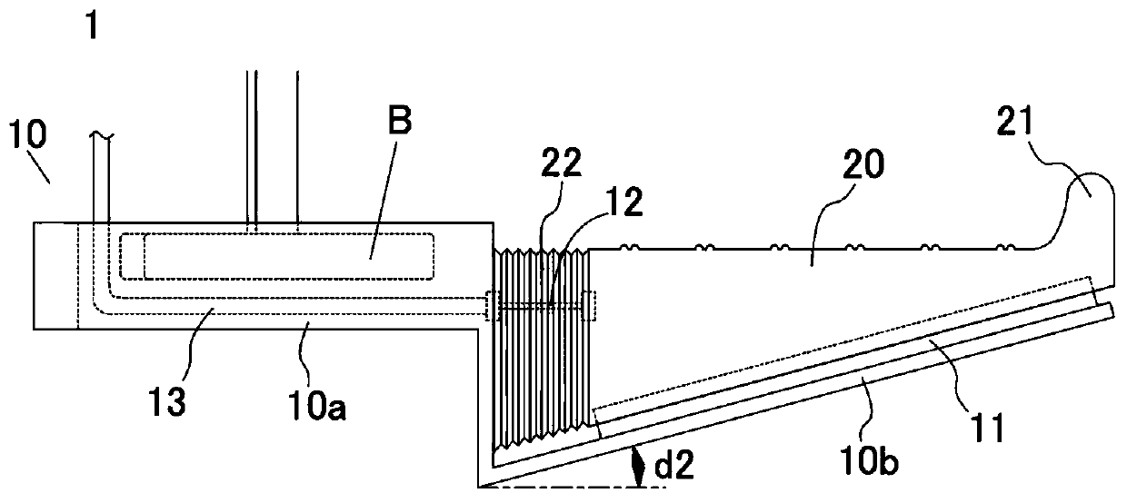
[0025] Hereinafter, one embodiment of the present invention will be described based on the drawings. figure 1 It is a perspective view showing an embodiment of the pedal device according to the present invention, figure 2 for top view, image 3 for from figure 2 The front view viewed in the direction of the arrow V. Figure 4 It is a side view of a state in which the pedal device 1 is attached to an existing brake pedal B and used as seen from the right side. also, Figure 5 to Figure 8 It is a diagram showing the operation and action of the pedal device 1, Figure 5 It is a top view when accelerating (accelerator is on), Figure 6 main view, Figure 7 is the top view when braking (accelerator off), Figure 8 main view.

[0026] The pedal device 1 is composed of a frame 10, an accelerator pedal pad 20, and a cable 12. The frame 10 extends downward from the right side of a substantially box-shaped bracket 10a, and extends downward from a base 10b, which is a rectangul...


PUM


Abstract

To provide a small-size, simply-structured, and low-cost one-pedal type pedal apparatus that is easily mountable to an existing brake pedal without modifying the brake pedal, and that does not extendthe pedal tread toward a driver side, enables a brake and an accelerator to be operated even in a state where the right foot heel is placed on a floor, and permits slight misalignment of a pedal treading position by surely being operated in an accelerator closing direction during braking. This pedal apparatus is provided with: a frame that comprises a bracket mountable to an existing brake pedal,and a base extended rightward from the bracket; an accelerator pad that is mounted so as to be slidable left and right on the base via a slide mechanism provided to the upper surface of the base; anda transmission means for transmitting the position of the accelerator pad to an automobile accelerator device. The pedal apparatus is characterized in that the base is arranged so as to incline downward toward the bracket, the accelerator pad has a shape in which a tread is lower than the tread of the brake pedal in a state where the accelerator pad is set at the leftmost position, a biasing meansfor biasing the accelerator pad leftward is provided, and the base is provided to the bracket at an angle where the right end of the base is closer to the driver side.

Description

technical field [0001] The present invention relates to a pedal device of a so-called "one pedal" type integrally equipped with a brake operating mechanism and an accelerator operating mechanism of an automobile, and more specifically relates to a pedal device in which an existing accelerator pedal is removed. Basically, a pedal device that can operate the brake and the accelerator with a single pedal by being attached to an existing brake pedal and connected to an accelerator operating mechanism. Background technique [0002] As a so-called "one-pedal" type pedal device, there is known a pedal device in which an accelerator operating mechanism operable in left and right directions by a toe is integrally provided with a brake pedal stepped forward by a driver. According to such a structure, the driver does not have to step on the brake pedal and the accelerator pedal alternately, so not only can the idling time when emergency braking is required to shorten the braking distan...

Claims


Application Information

Patent Timeline
Patent Type & Authority Applications(China)
IPC IPC(8): B60T7/04B60K26/02G05G1/01G05G1/30
CPCB60T7/06B60K26/02B60T7/02B60T7/04G05G1/01G05G1/305G05G1/42G05G1/44B60Y2302/09G05G1/30G05G1/36G05G1/38G05G1/487
Inventor 常深和生
Owner 常深和生
Why Eureka
Try Eureka