Pump apparatus

a technology of pumping apparatus and pumping chamber, which is applied in the direction of pumping chamber, positive displacement liquid engine, liquid fuel engine, etc., can solve the problems of driving chamber, and achieve the effect of simplifying structure and facilitating production

Active Publication Date: 2005-09-22
AMTEC CO LTD +2
View PDF4 Cites 2 Cited by
  • Summary
  • Abstract
  • Description
  • Claims
  • Application Information

AI Technical Summary

Benefits of technology

[0009] The present invention solves the above problem by providing a pump apparatus which can normally function in the initial pumping operation without any adjustments being made, and which has a simplified structure for easier production thereof.

Problems solved by technology

However, in an initial state of the pumping operation, since air exists in the pump system, the internal pressure (liquid pressure) in the driving chamber 100b is insufficient and a frictional resistance in a dry state is caused between the shuttle 112 and the cylindrical hole 111.

Method used


Image

  • Pump apparatus
  • Pump apparatus
  • Pump apparatus

Examples


Embodiment Construction

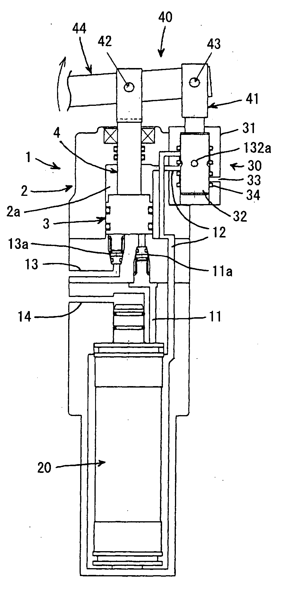
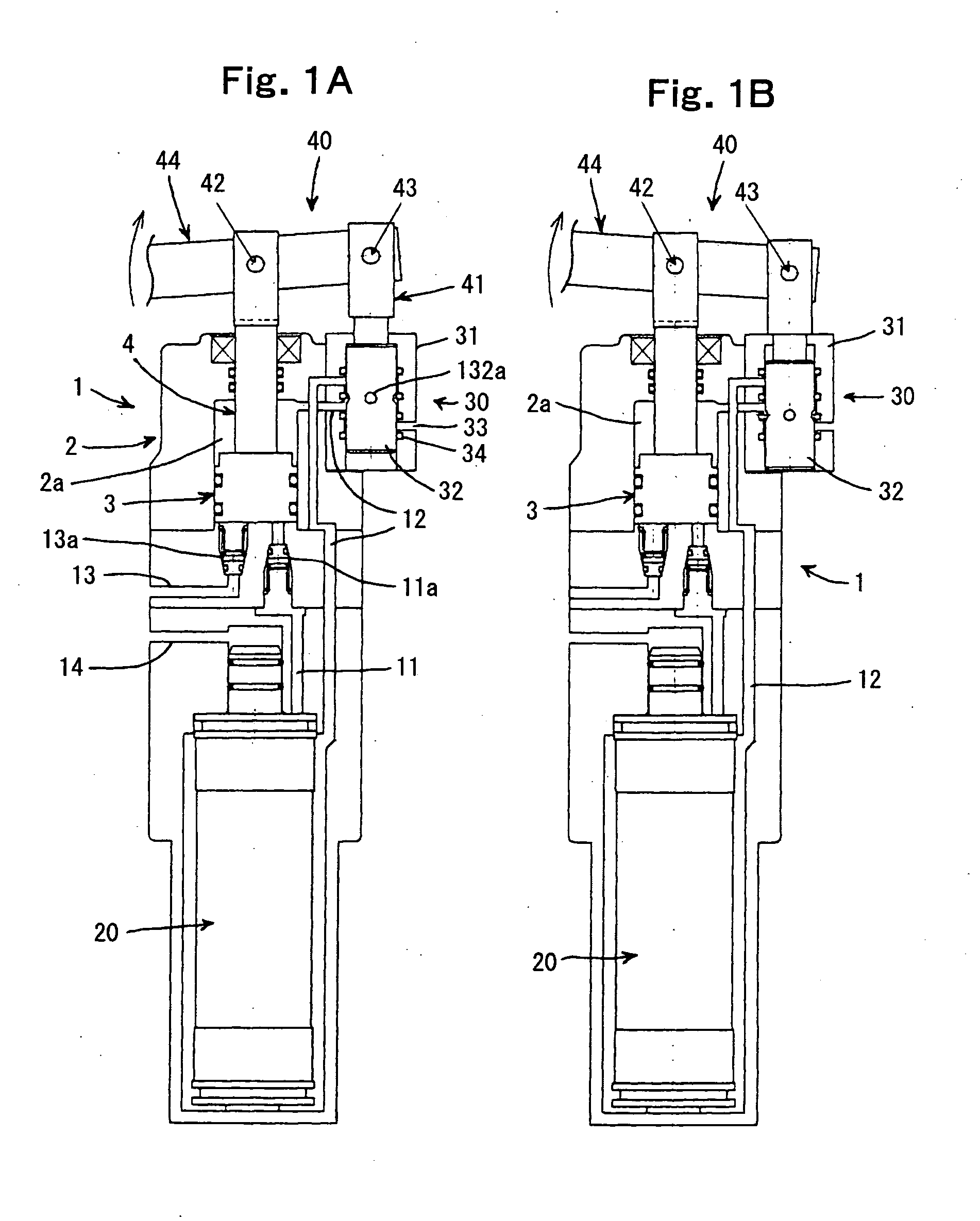
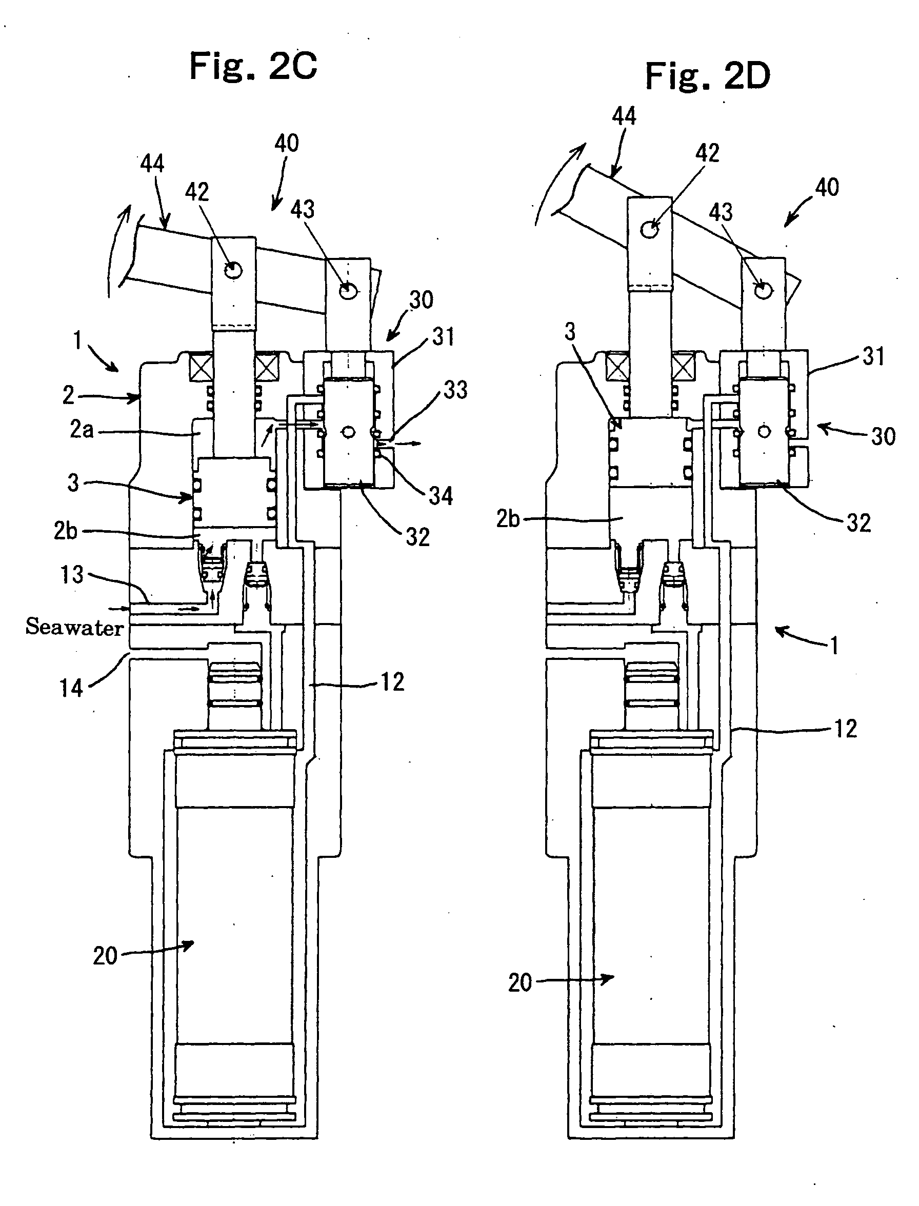
[0028] A pump apparatus of the present invention provides a pump body including a cylinder, a piston reciprocably moving in the cylinder, and a piston rod having two ends, one end connected to the piston and the other end projecting outward from the cylinder, in which the piston moves up to suck fluid from outside of the cylinder into a pumping chamber in the cylinder through a suction passage and discharge fluid in a pumping driving chamber in the cylinder to outside of the cylinder through an external discharge passage, while the piston moves down to send the fluid in the pumping chamber to an external fluid-sending destination through a sending-out passage and circulate a portion of the fluid sent to the fluid-sending destination into the pumping driving chamber through a circulation passage, the pump apparatus comprising: a switching valve provided in the circulation passage; and a link mechanism for driving the switching valve and the piston rod, wherein the switching valve inc...


PUM


Abstract

In a pump apparatus of the present invention, a portion of fluid sent to a fluid-sending destination is circulated to a pumping driving chamber on one side of a cylinder through a circulation passage. The pump apparatus includes a switching valve which switches inflow and outflow of the circulated fluid with respect to the pumping driving chamber. The switching valve is connected to a piston rod through a link mechanism, and mechanically carries out the switching operation using a pumping driving force.

Description

CROSS-REFERENCE TO RELATED APPLICATION [0001] This application is related to Japanese application No. 2004-74832 filed on Mar. 16, 2004, whose priority is claimed under 35 USC §119, the disclosure of which is incorporated by reference in its entirety. BACKGROUND OF THE INVENTION [0002] 1. Field of the Invention [0003] The present invention relates to a pump apparatus and, more particularly, to a pump apparatus capable of obtaining a high discharge pressure with a low driving pressure and is used when seawater or dirty water is allowed to pass through a semipermeable membrane, e.g., a reverse osmosis membrane to obtain drinking water. [0004] 2. Description of the Related Art [0005] As shown in FIGS. 8 and 9, a conventionally known pump apparatus (e.g., JP-B 3-21208 (1991)) of this kind comprises a pump body 100 having a cylinder 101 and a plunger 102, a manual lever (not shown) which allows the plunger 102 to reciprocate in the cylinder 101, a filter (reverse osmosis membrane) 130, a...

Claims


Application Information

Patent Timeline
Patent Type & Authority Applications(United States)
IPC IPC(8): F04B53/10B01D61/08B01D61/10F04B1/00F04B9/02F04B9/103F04B9/107F04B9/14F04B23/00F04B53/14
CPCB01D61/10F04B9/14F04B9/107F04B53/10F04B53/14
Inventor HOSOKAWA, MASAYUKISHINTAKU, FUMIHIRO
Owner AMTEC CO LTD
Why Eureka
Try Eureka