Dose indicators and dispensing canister-indicator assemblies

a technology of dose indicators and canisters, applied in the direction of instruments, caps, liquid handling, etc., can solve the problems of inability to precisely determine the amount of medicaments in the container at any given time, and inability to accurately measure the amount of medicaments in the container, etc., to achieve convenient use, facilitate production and handling, and reduce the effect of tampering

Inactive Publication Date: 2005-09-22
3M INNOVATIVE PROPERTIES CO
View PDF23 Cites 50 Cited by
  • Summary
  • Abstract
  • Description
  • Claims
  • Application Information

AI Technical Summary

Benefits of technology

[0025] Annular dose indicators according to the invention are advantageous in that the indicator can be manufactured independent of the dispensing-canister and the adaptor to provide a self-contained assembly. They can be easily mounted around the dispensing canister by sliding the indicator over the outlet- or container-end of the dispensing canister, as the case may be. This simplifies the production and handling of the indicator itself as well as the assembly of a complete dispenser or a dispensing-canister / indicator assembly. Production is also simplified in that the dose indicators according to the invention and in particular certain preferred embodiments thereof include a limited number of components. Because the counter-ring and driving member are located or mounted within the housing of the indicator, the sensitive components of the indicator are protected, providing desirable robustness, ease in handling as well as resistance to tampering during use.
[0026] In use, dose indicators according to the invention are located substantially about the dispensing-canister and above the outlet means, and thus the indicator can be advantageously used in both press-and-breathe inhalers and breath-actuated inhalers, in which the triggering or breath actuation mechanism is located near or about the support of the adaptor. Also because the indicators are positioned about the dispensing-canister, so that the first edge of indicator, which faces towards the closed end of the container, does not extend axially beyond the closed end of the container, a necessary increase in axial dimensions can be avoided, which is particularly advantageous in a portable inhaler.
[0027] Dose indicators according to the invention can be readily used with various types of dispensing canisters. Certain preferred embodiments of the dose indicator are particularly advantageous for use with dispensing canisters having a container, whose diameter of its outermost circumference is greater than the diameter of the outermost circumference of the ferrule and / or a container having a constricted portion, if applicable near or adjacent to the ferrule (distant to the outlet member). Here the space formed by the recess in the dispensing-canister-profile can be advantageously used for the components of the dose indicator, for example the counter-ring and thus the overall dimensions of the counter-ring and / or indicator can be kept in relation to the dispensing-canister to aminimum. Containing the dose indicator within the profile of the dispensing canister may also have an additional advantage of interfering less with the airflow through and within a dispenser or adaptor. In particular for use with such canisters, it is preferred that the diameter of the outermost circumference of the counter-ring is less than the diameter of the outermost circumference of the container.

Problems solved by technology

However, this method is necessarily far from precise and is even less satisfactory with a breath-actuated inhaler in which, because of the additional parts, the mass of the aerosol contents is a smaller proportion of the total unit weight.
Thus, a difficulty arising from use of such known devices is that the patient cannot precisely determine the amount of medicament in the container at any given time.
In extreme cases, a patient, possibly in an emergency situation and requiring an immediate dose of medicament, may find that the container will not dispense a dose because its contents have already been exhausted.
Although a number of dose counters or indicators for metered dose medicinal products have been proposed over the last decade, no pressurized metered dose inhaler with a built in dose counter has yet been marketed.
Such counters can be disadvantageous in that they are relatively expensive.
Accordingly the reliability of such counters is overshadowed by the reliability of the power source itself.
If during this extended period the power source is exhausted or runs out, the patient would be again faced with uncertainty about the precise number of doses contained in the device.
This makes mass production and assembly often complicated and / or tedious.
Such add-on counters suffer a number of disadvantages, including increased overall dimensions of the device resulting in a reduced ease in handling of the device.
Such arrangements can be disadvantageous in that modification of the adaptor geometry, such as greater dimensions, in the critical region where atomization takes place is generally required.
Furthermore, such counters are often not applicable for breath-actuated devices, because this region usually contains the trigger mechanism for the breath-actuated firing of the device.
WO 93 / 24167 for example proposes actuating means for triggering breath-actuated firing with an associated dose indicator as a type of add-on system at the end of the dispensing canister distant to the outlet member, which disadvantageously increases the overall dimensions of the device and correspondingly reduces general handleability of the device.
Another problem is that many dose counters do not differentiate between the same container being removed and put back in the adaptor (e.g. for cleaning) and a new container being inserted as a replacement, so that the count may or may not properly reset to the beginning.

Method used


Image

  • Dose indicators and dispensing canister-indicator assemblies
  • Dose indicators and dispensing canister-indicator assemblies
  • Dose indicators and dispensing canister-indicator assemblies

Examples


Embodiment Construction

[0063] It is to be understood that the present invention covers all combinations of particular and preferred aspects of the invention described herein.

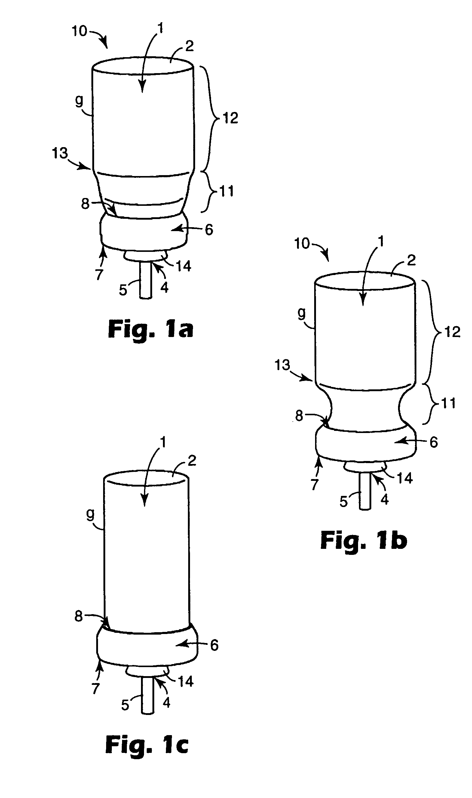
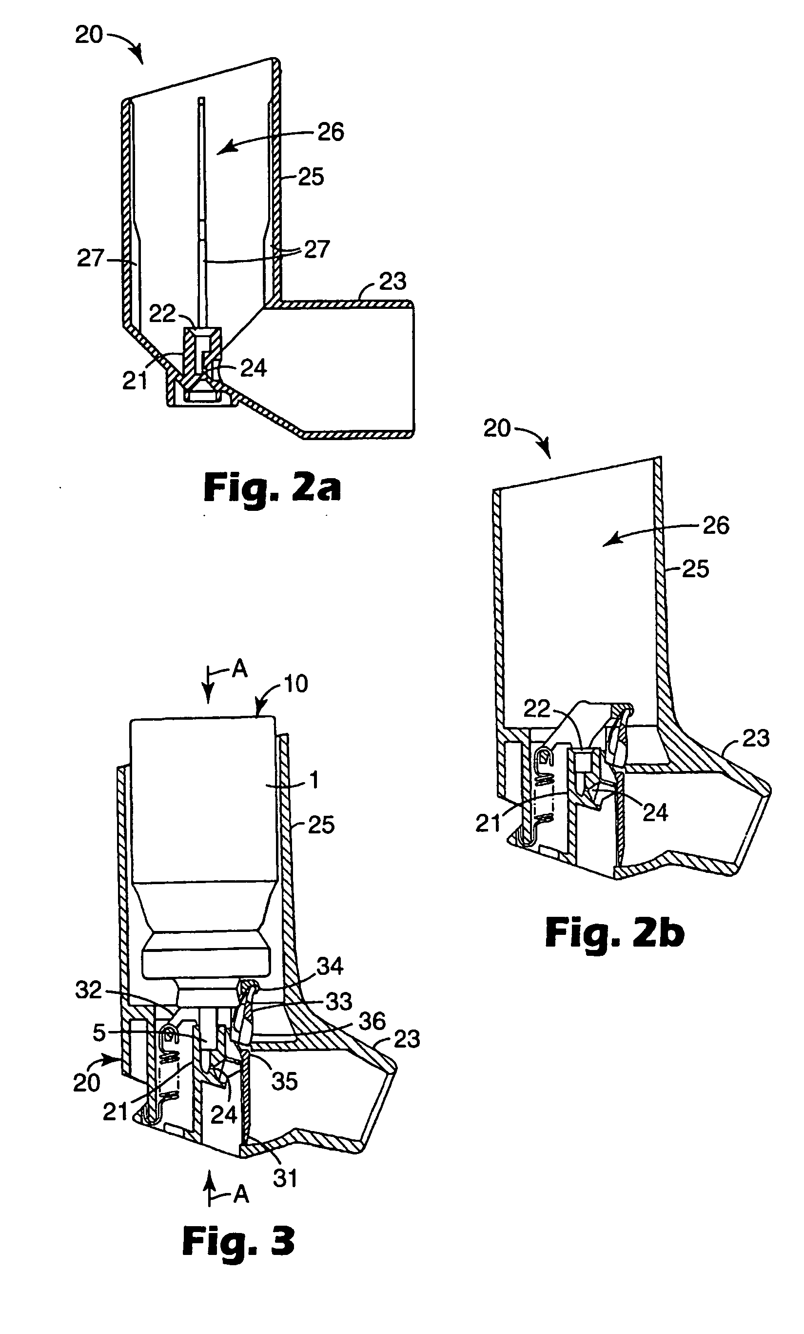
[0064] For a better understanding of the various aspects of the present invention, exemplary dispensing canisters suitable for use with the present invention as well as two exemplary conventional adaptors will be initially described in the following.

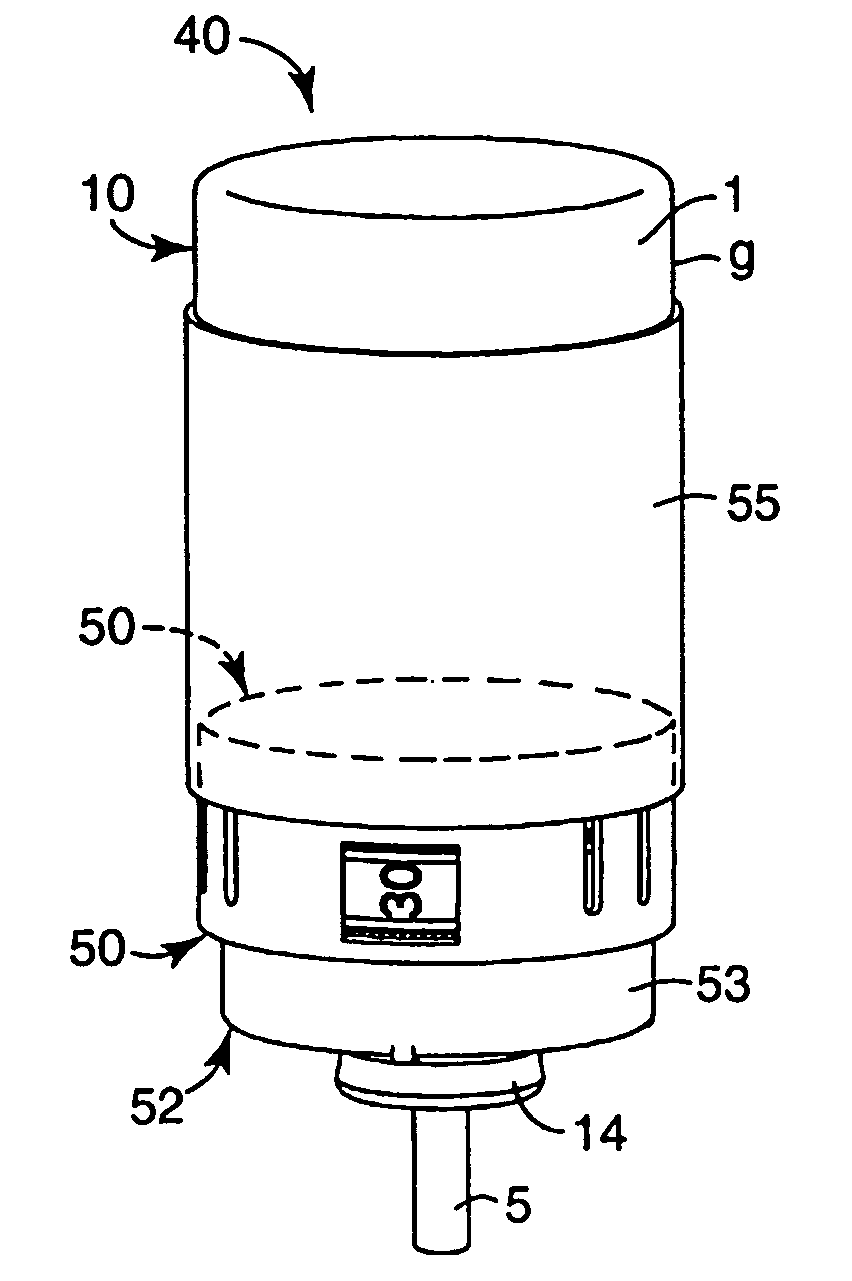
[0065] In FIGS. 1a to c three exemplary dispensing-canisters are illustrated. A dispensing canister (10) typically comprises a substantially cylindrical container (1), in particular an aerosol container, having a closed end (2), an open end (3, not visible) and a side-wall (9). The open end of the container is equipped with a dispensing means (4), in particular, a dispensing valve, more particularly a metering dose valve, having an elongate outlet member (5), in particular a valve stem, movable between closed and discharged positions. The dispensing means is normally mounted onto the con...


PUM


Abstract

An annular dose indicator (50) for use with a dispenser comprising a dispensing canister (10) comprising a substantially cylindrical container (1) having a closed end (2) and an open end (3), said open end of the container being equipped with a dispensing means (4) that comprises an outlet member (5) movable between closed and discharge positions and an adaptor comprising a support block (21) having a socket (22) adapted to receive the outlet member, the container and support block being reciprocally movable relative to each other to cause the outlet member to move to its discharge position thereby dispensing a dose, said annular dose indicator (50) comprising an annular housing (60) having an interior surface (64) defining a substantially circumferential cavity; a counter-ring (80), said counter-ring located in the cavity and being arranged to be moveable relative to the housing by rotation about an axis parallel or substantially parallel to linear reciprocal movement of container and support block; a driving member (90) mounted on the interior surface of the housing, said driving member engaging the counter-ring and being arranged to be selectively engaged during reciprocal movement of container and support block as to drive an incremental, rotational movement of the counter-ring; wherein said indicator (50) is arranged to be circumferentially mountable about the dispensing-canister (10), such that the first edge (51) of the indicator faces towards the closed end of the container, the second edge (52) of the indicator faces towards the outlet of the dispensing canister, so that at least the outlet member of the canister will extend beyond the second edge of the indicator.

Description

FIELD OF THE INVENTION [0001] The present invention relates to annular mechanical dose indicators, particularly suitable for use with medicinal dispensers, more particularly metered dose inhalers. The present invention also relates to dispensing canister-indicator assemblies, in particular such assemblies including medicinal aerosol dispensing canisters, more particular pressurized metered dose dispensing canisters, as well as dispensers comprising such dispensing canister-indicator assemblies. BACKGROUND OF THE INVENTION [0002] Inhalation therapy is becoming an increasingly important method of administering medicaments to a patient. The medicament is generally formulated with suitable propellant and if appropriate other components and charged into a container, e.g. an aerosol vial. The container is typically fitted by means of a ferrule with a dispensing means, such a valve, in particular a metered dose valve, comprising an elongate outlet member (e.g. a valve stem) movable between...

Claims


Application Information

Patent Timeline
Patent Type & Authority Applications(United States)
IPC IPC(8): A61J7/04A61M15/00G06M1/04G06M1/08
CPCA61M15/009A61M15/0091A61M15/0073A61M15/0068G06M1/04A61M15/0096
Inventor MARX, EDUARD
Owner 3M INNOVATIVE PROPERTIES CO
Why Eureka
Try Eureka