Transmission device for two or more shafts

a technology of transmission device and shaft, which is applied in the direction of mechanical equipment, belt/chain/gearing, differential gearing, etc., can solve the problems of inability to transmit high torque, size problems of the same device, and large device, and achieve the effect of low torque, high torque, and easy adaptation

a technology of transmission device and shaft, which is applied in the direction of mechanical equipment, belt/chain/gearing, differential gearing, etc., can solve the problems of inability to transmit high torque, size problems of the same device, and large device, and achieve the effect of low torque, high torque, and easy adaptation

US20050211527A1Active Publication Date: 2005-09-29BI CI DI

Image

  • Transmission device for two or more shafts
  • Transmission device for two or more shafts
  • Transmission device for two or more shafts

Examples


Embodiment Construction

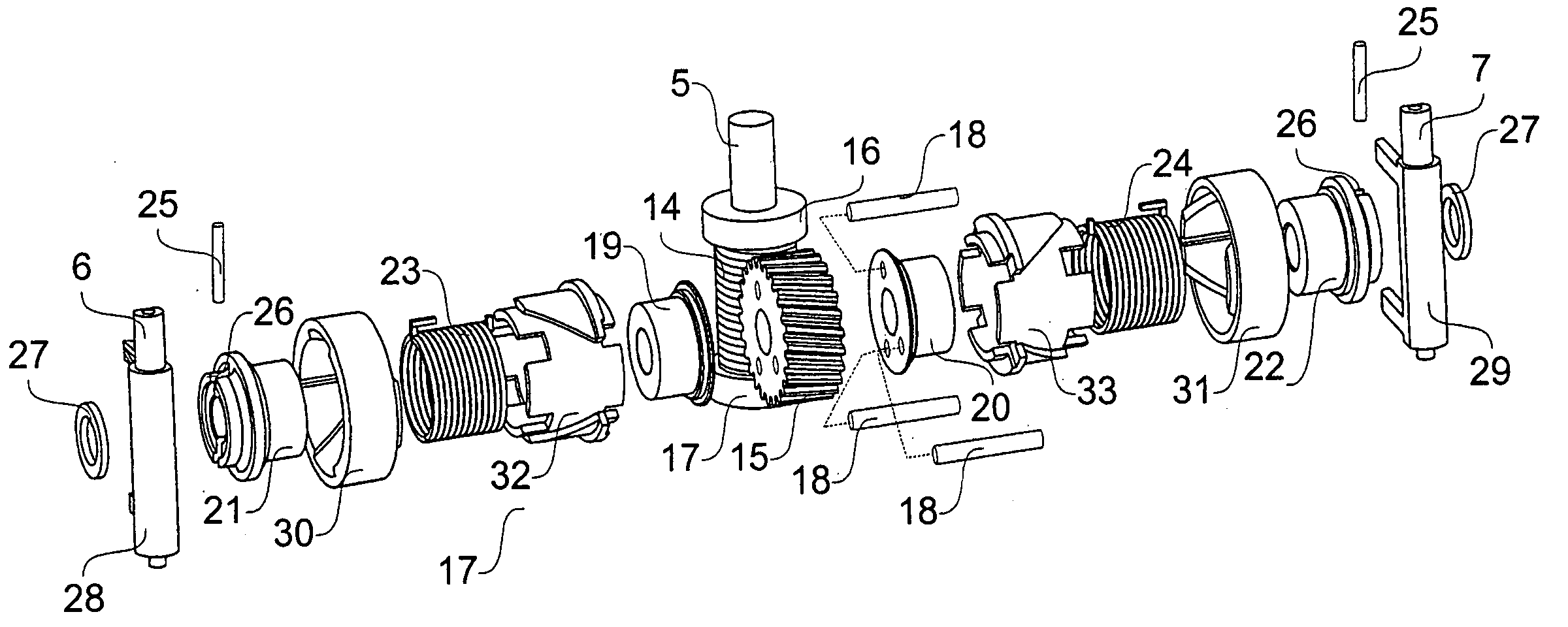
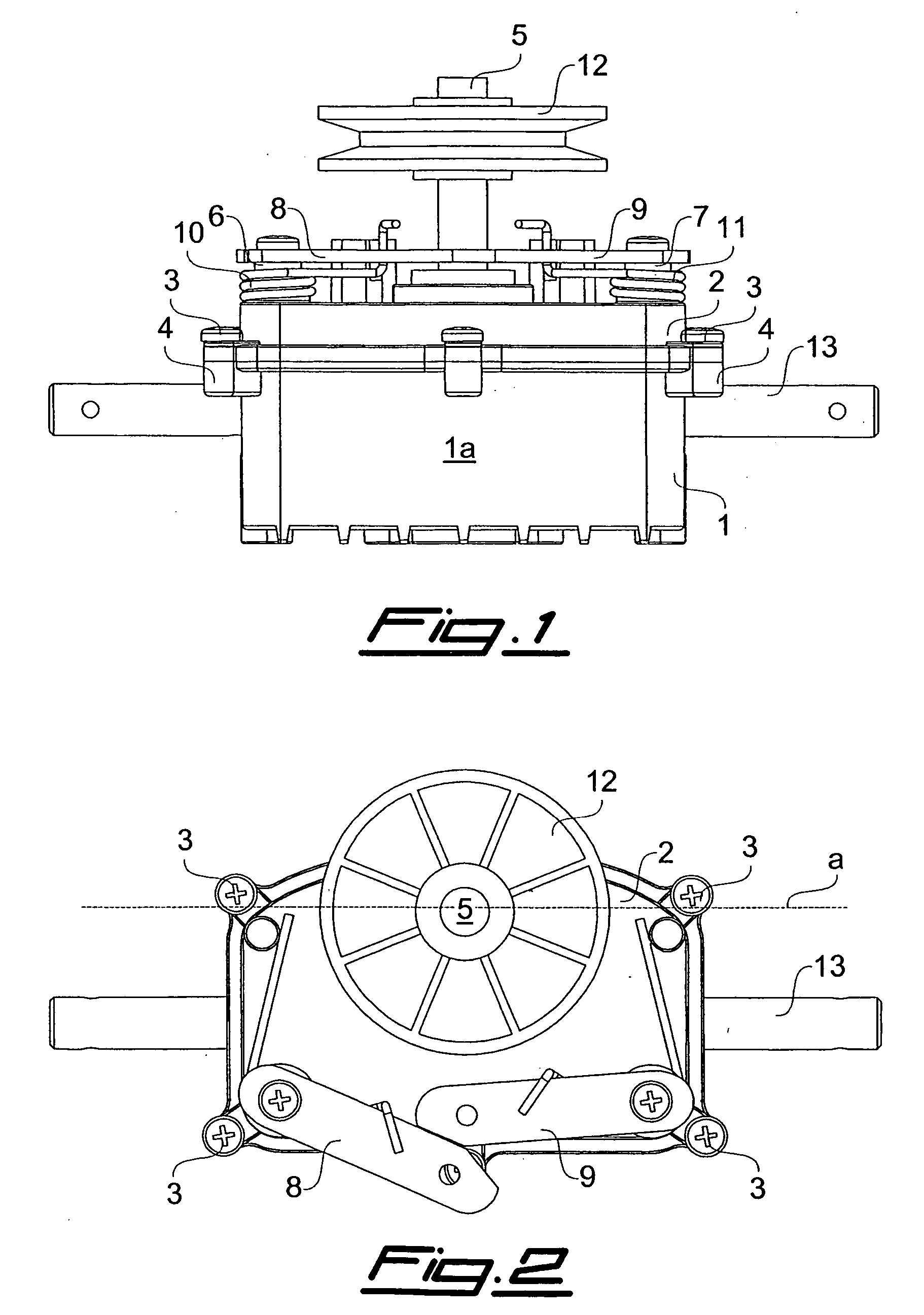
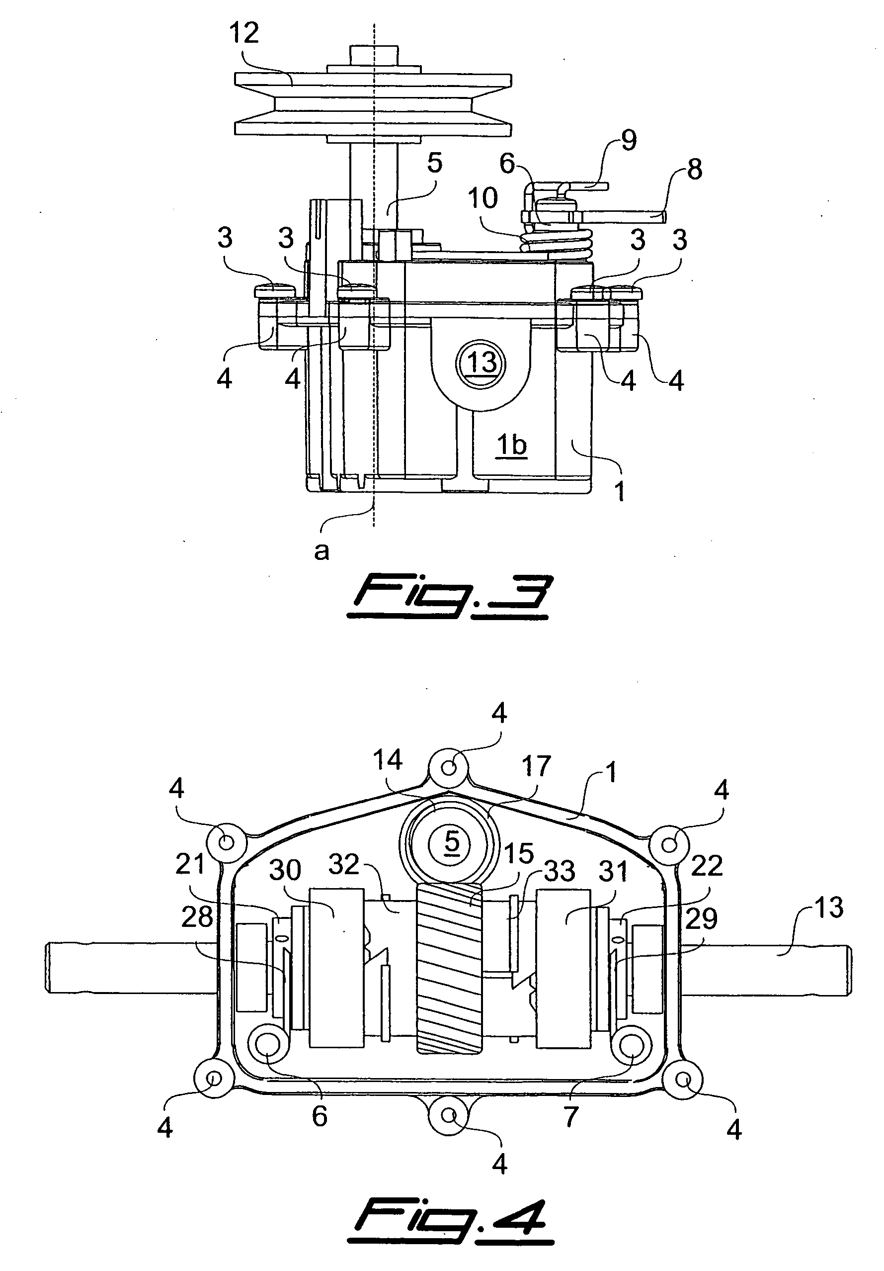
[0022] Referring to FIGS. 1 to 3, it is seen that the device according to the present invention comprises a container 1 which is closed by an upper cover 2 by means of a plurality of screws 3 inserted into corresponding seats 4 arranged along the upper edges of container 1. The container has a substantially prismatic shape with a pentagonal base, wherein the front wall 1a is substantially perpendicular to the two lateral walls 1b. Cover 2 is provided with a hole in which a first shaft 5 is inserted, in particular a drive shaft, as well as with two other holes, close to the front wall 1a, in which two control shafts 6, 7 are inserted. Control levers 8, 9 urged outside container 1 by springs 10, 11 can be keyed on these control shafts 6, 7, while a transmission member 12, for example a pulley, can be keyed on the drive shaft 5. A second shaft 13, in particular a driven shaft, is instead arranged perpendicular to shaft 5 and crosses both lateral walls 1b of container 1. The first shaft...


PUM


Abstract

A transmission device for two or more shafts is provided having two first cylindrical sleeves which are connected to the first shaft and can be mechanically coupled or uncoupled with two second cylindrical sleeves connected to the second shaft or to a third shaft aligned with the second shaft, by tightening or loosening, respectively, two helical springs arranged in a substantially coaxial manner astride these cylindrical sleeves. Two control collars are mechanically coupled with two tubular members, so that the mutual translation of the control collars with respect to the tubular members also causes their mutual rotation, the ends of the helical springs being arranged into seats made in the control collars and in the tubular members so that their mutual rotation tightens or loosens the coils of the helical springs, thereby causing the coupling or the uncoupling, respectively, between the first cylindrical sleeves and the second cylindrical sleeves.

Description

FIELD OF THE INVENTION [0001] The present invention relates to a transmission device for two or more shafts, and in particular to a clutch-type mechanical transmission device with helical springs for transmitting a torque from a shaft to one or more shafts. BACKGROUND [0002] Italian patent 1311501 discloses a transmission device which comprises a first cylindrical sleeve which can be mechanically coupled or uncoupled with a second cylindrical sleeve by tightening or loosening, respectively, a helical spring arranged in a substantially coaxial manner astride these two cylindrical sleeves, wherein a control collar is mechanically coupled with a tubular member, so that the mutual translation of the control collar with respect to the tubular member also causes their mutual rotation, the ends of the helical springs being arranged into seats made in the control collar and in the tubular member so that their mutual rotation tightens or loosens the coils of the helical spring, thereby causi...

Claims


Application Information

Patent Timeline
29 Sep 2005
Publication
US20050211527A1
IPC
F16D13/02
CPC
F16D13/025; Y10T74/19005; F16H48/12
Inventors
CIBIEN, ANGELO