Agitator, a circulatory cleaning device attached to the agitator, and a circulatory line system comprising the circulatory cleaning device

Inactive Publication Date: 2005-10-20
KANSAI PAINT CO LTD
View PDF20 Cites 23 Cited by
  • Summary
  • Abstract
  • Description
  • Claims
  • Application Information

AI Technical Summary

Benefits of technology

[0012] However, the heating generated by the friction between the grinding medium and the rotor or vessel inside a bead mill and the friction within the grinding medium is greater than the cooling provided by the vessel of the bead m

Problems solved by technology

However, the heating generated by the friction between the grinding medium and the rotor or vessel inside a bead mi

Method used


Image

  • Agitator, a circulatory cleaning device attached to the agitator, and a circulatory line system comprising the circulatory cleaning device
  • Agitator, a circulatory cleaning device attached to the agitator, and a circulatory line system comprising the circulatory cleaning device
  • Agitator, a circulatory cleaning device attached to the agitator, and a circulatory line system comprising the circulatory cleaning device

Examples


first embodiment

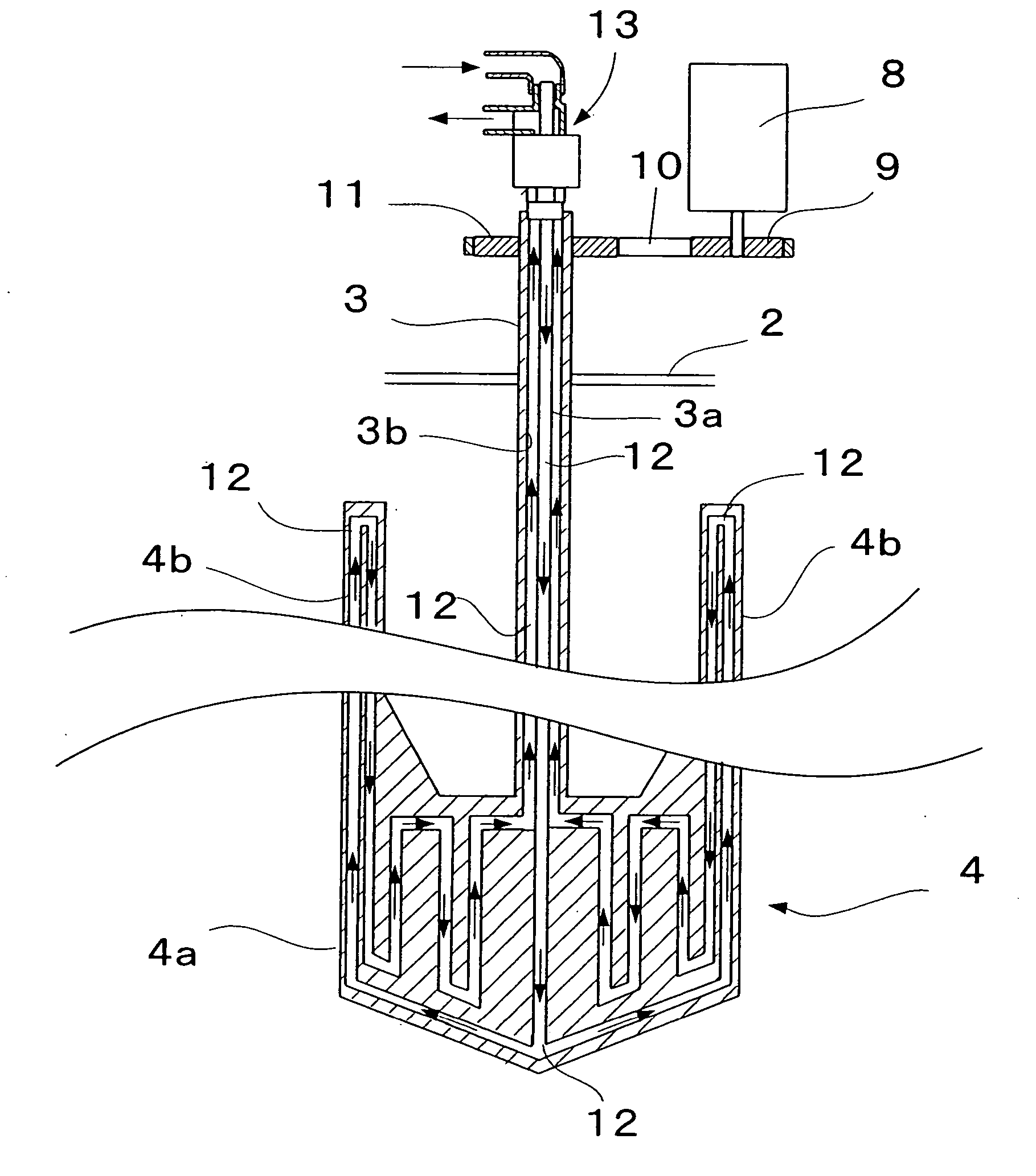
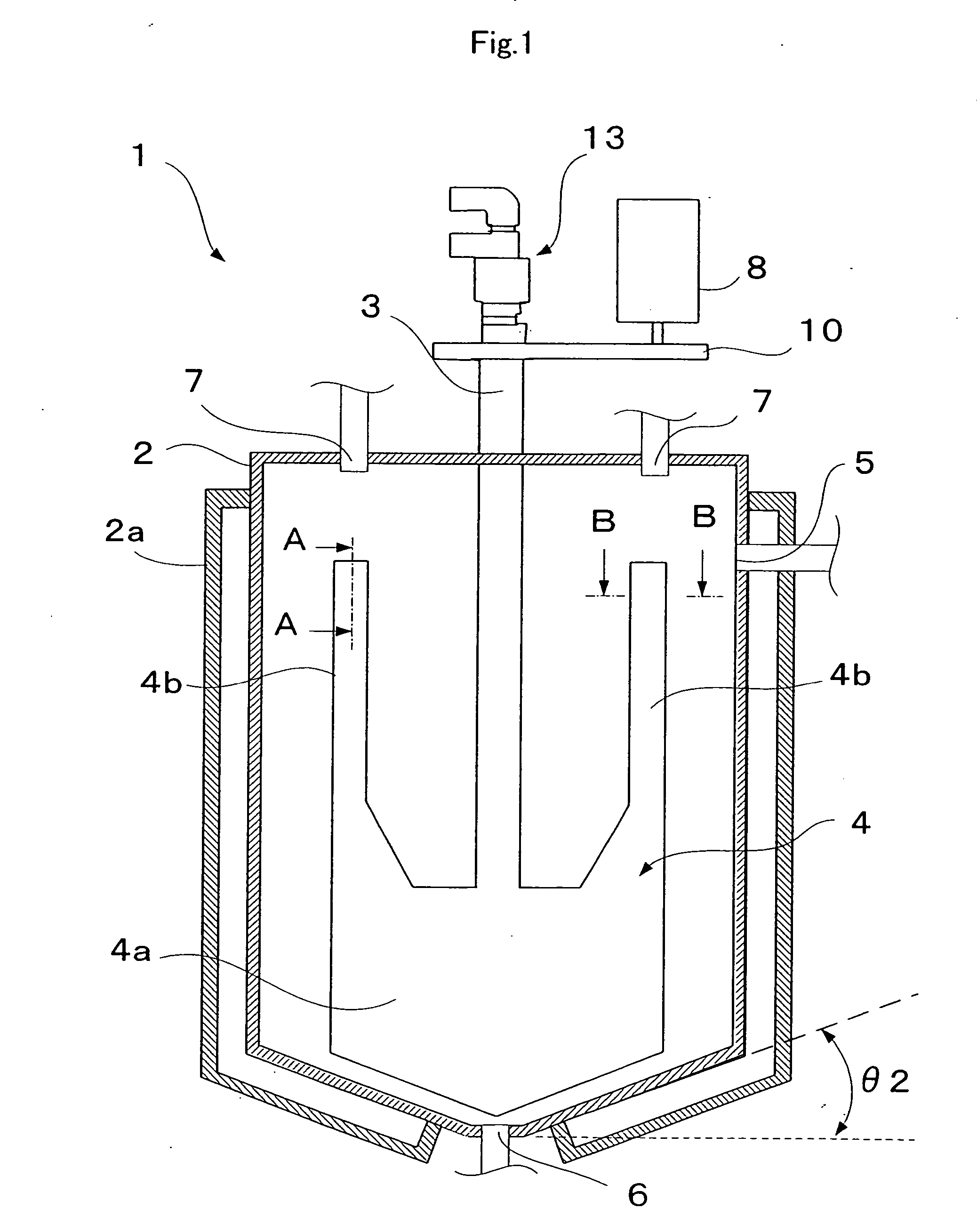
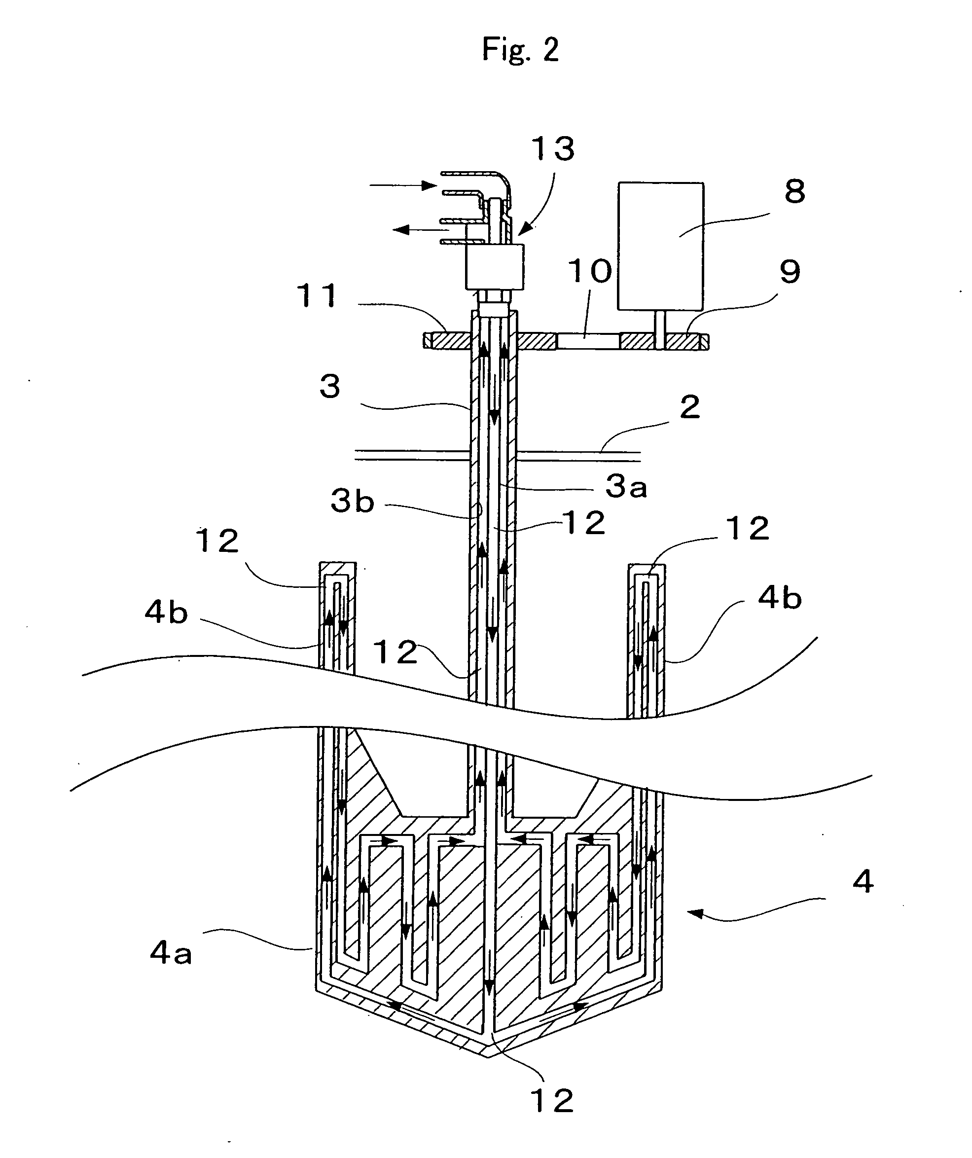
[0048] an agitator according to the present invention will be described with reference to FIGS. 1-3 below. FIG. 1 is a longitudinal sectional view showing the inner structure of the agitator, and FIG. 2 is a partial longitudinal sectional view showing the inner structure of the flat paddle blade part of FIG. 1.

[0049] The agitator 1 has an agitating vessel 2; a rotating shaft 3 extending vertically in the inner center of the agitating vessel 2; and a flat paddle blade 4 as an agitating blade mounted on the rotating shaft 3.

[0050] The agitating vessel 2 comprises a fluid inlet 5 in an upper part thereof and a fluid outlet 6 at the bottom. It has a cylindrical circumferential side face and a coolant jacket 2a therearound.

[0051] The coolant jacket can be of a known constitution, and allows a coolant medium such as a coolant water to circulate inside. The configuration of the bottom of the agitating vessel 2 is a truncated cone with the narrow portion downwards. Moreover, the agitating...

second embodiment

[0064] According to the present invention, the flat paddle blade 4 has, as shown in the cross sectional configurations of FIGS. 4 and 5, a peripheral portion which is entirely tapered by inclined surfaces 4c, 4c formed two sides and has a V-shaped cross sectional configuration. In the examples shown in FIGS. 4 and 5, the inclined surfaces 4c, 4c are flat surfaces, but they can also be formed by curving faces as shown in the cross-sectional view of FIG. 6. Moreover, the tip tapered by the inclined surfaces 4c, 4c, is illustrated as a sharp point in the examples shown in FIGS. 4 and 5, but can be, for example, of rounded U-shaped cross sectional configuration shown in FIG. 6. It should be noted that the cross sectional configuration of only the upper flat paddle blade portion 4b is shown in FIGS. 4-6, but the case for the bottom flat paddle blade portion 4a is also the same.

[0065] The agitators of the aforementioned first and second embodiments are mainly used incorporated into a circ...


PUM


Abstract

An agitator able to mix and disperse a variety of fluids of various fluid volumes with different viscosities ranging from low to high, and having excellent, cleanability and improved cooling efficiency is provided. The agitator comprises a rotating shaft 3 extending vertically inside an agitating vessel 2, and a flat paddle blade 4 mounted on the rotating shaft 3. The flat paddle blade has a bottom flat paddle blade portion 4a extending outwards from the bottom of the rotating shaft 3 and a rectangular upper flat paddle blade portion 4b extending upward from an upper part of each side end of the bottom flat paddle blade portion 4a. The dimensional ratio (b/a) of the blade diameter (b) of the bottom flat paddle blade portion 4a to the inner diameter (a) of the agitating vessel 2 is from 0.6 to 0.9, and the dimensional ratio (d/c) of the height (d) of an upper flat paddle blade portion 4b to the height (c) of the bottom flat paddle blade portion 4a is from 1 to 4. A passage 12 is formed inside the rotating shaft 3 and flat paddle blade 4 for passing a coolant medium therethrough.

Description

TECHNICAL FIELD [0001] The present invention relates to an agitator, a circulatory cleaning device attached to the agitator, and a circulatory line system comprising the circulatory cleaning device. BACKGROUND ART [0002] Conventionally, coating compositions, inks and like coloring liquids are clear varnishes containing pigment pastes. Pigment pastes are generally prepared by the steps of mixing pigments, resins, organic solvents, and like raw materials in an agitator to prepare a mill base, and then passing this mill base a few times through a bead mill dispersion apparatus or like continuous dispersion apparatus to disperse the pigment. [0003] Specifically, the commonly employed pigment dispersion method comprises the steps of feeding an unprocessed pigment paste stored in a feeding vessel to a dispersion apparatus, temporarily storing the pigment paste obtained by dispersing it in the dispersion apparatus in a receiving vessel, returning the pigment paste stored in the receiving v...

Claims


Application Information

Patent Timeline
IPC IPC(8): B01F27/906B08B3/02
CPCB01F5/104B01F7/00116B01F7/00141B01F7/0015B01F7/00266B01F7/00291B01F2015/061B01F7/20B01F13/1047B01F15/00032B01F15/065B01F15/068B01F7/18B01F25/52B01F27/0721B01F27/0724B01F27/0725B01F27/1122B01F27/1125B01F27/906B01F27/90B01F33/831B01F35/1453B01F2035/98B01F35/95B01F35/92
Inventor MATSUMOTO, HIROYUKIKURAMOTO, MUTSUOHIRAKI, MASAHIKO
Owner KANSAI PAINT CO LTD
Why Eureka
Try Eureka