Information recording method, information recording medium and information recording apparatus

a technology of information recording and information recording medium, applied in the field of information recording methods and apparatuses, can solve the problems of inability to meet the requirements of the proposed method, limited in the achievable recording densities, and becomes more difficult to secure the recording compatibility therebetween, so as to prevent distortion of the shape of the recording mark, increase linear density, and improve the effect of linear density

Inactive Publication Date: 2005-11-03
HITACHI CONSUMER ELECTRONICS CORP
View PDF18 Cites 18 Cited by
  • Summary
  • Abstract
  • Description
  • Claims
  • Application Information

AI Technical Summary

Benefits of technology

[0008] In particular, in the case of a DVD-RAM having a recording capacity of 4.7 GB higher in density than a DVD-RAM having a recording capacity of 2.6 GB, when recording is carried out with the same spot diameter as in the 2.6 GB DVD-RAM, compatibility with the 2.6 GB DVD-RAM can be achieved more easily. However, as a linear density is increased with the same spot used, a spacing between positions at which two adjacent recording pulses are irradiated on the recording medium becomes smaller than the spot diameter of a laser beam on the medium. Therefore, since light distribution is overlapped when compared with the 2.6 GB case, it becomes necessary to prevent distortion of a recording mark shape caused by the overlapping. Moreover, when a space between recording marks is small, impossible separation between the marks with a reading beam spot causes a shift of a recording mark edge position of a reproduction signal waveform, it is also required to prevent such a shift. The edge position shifting way depends largely on the design of the recording medium, and the recording waveform suitable for a specific recording medium is not always suitable for another recording medium. In current circumstances, because of the increased linear density, the recording mark edge shift is increased by a mismatch between the recording medium and recording waveform to such a level as not to be negligible.
[0009] It is therefore an object of the present invention to provide a method and apparatus which can accurately record information with use of the same spot and can increase its density while attaining a compatibility. A related object of the present invention is to provide an information recording method, medium and apparatus which can stably record information on various sorts of recording media having different characteristics and also can easily secure a recording compatibility therebetween.

Problems solved by technology

However, methods proposed so far failed to satisfy the above condition sufficiently in their various recording waveforms and were limited in their achievable recording densities.
Thus as it is desired to obtain higher density recording, it becomes more difficult to secure a recording compatibility therebetween.
The edge position shifting way depends largely on the design of the recording medium, and the recording waveform suitable for a specific recording medium is not always suitable for another recording medium.

Method used


Image

  • Information recording method, information recording medium and information recording apparatus
  • Information recording method, information recording medium and information recording apparatus
  • Information recording method, information recording medium and information recording apparatus

Examples


Embodiment Construction

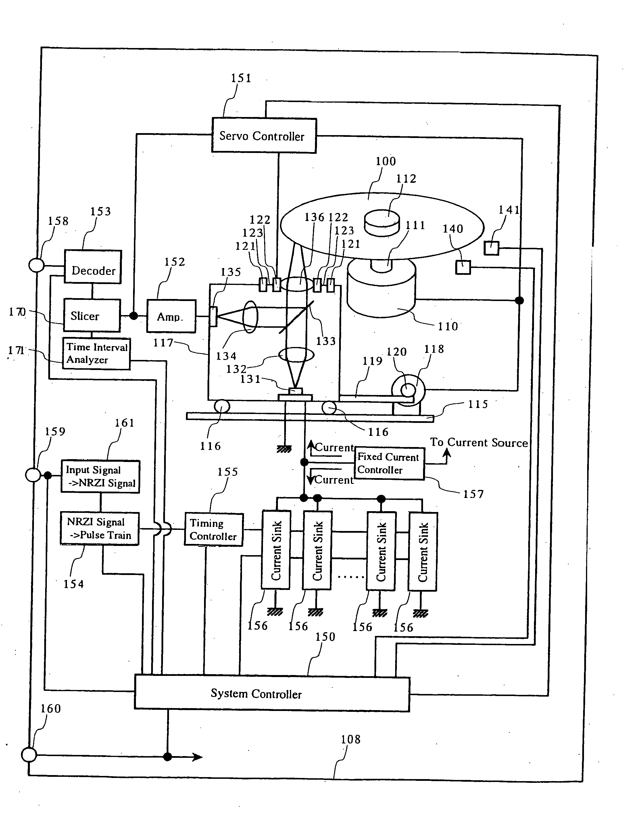
[0023] Explanation will be first be made as to reference numerals used herein.

[0024] Reference numeral 100 denotes a recording medium, 108 a casing, 110 a motor, 111 a rotary shaft, 112 a chucking mechanism, 115 a rail, 116 a rail guide, 117 a case, 118 a rotating motor,119 a linear gear, 120 a rotary gear, 121 a magnet, 122 a coil, 123 a suspension, 130 an objective lens, 131 semiconductor laser, 132 a collimating lens, 133 a beam splitter, 134 a detection lens, 135 a photodetector, 140 a detector, 141 a detection switch, 150 a system controller, 151 a servo controller, 152 a amplifier, 153 a decoder, 153 a decoder, 154 a signal processing circuit, 155 a timing controller or delay circuit, 156 a current sink, 157 a constant or fixed current controller, 158 a output connector, 159 an input connector, 160 a terminal, 161 a signal processing circuit.

[0025] The present invention will next be explained in accordance with embodiments which follow.

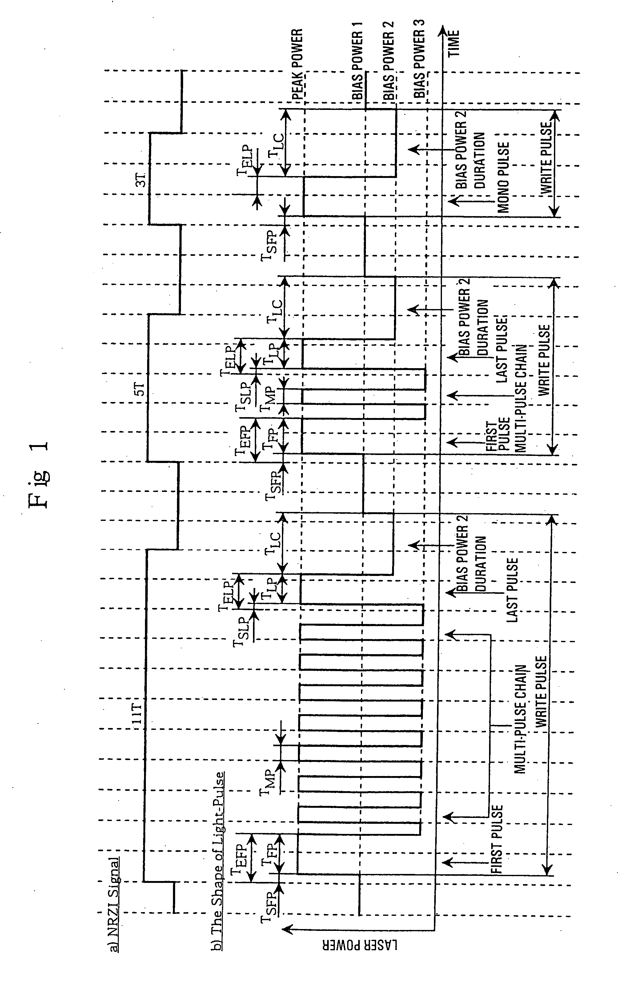
[0026] Shown in FIG. 1 are variations ...


PUM

PropertyMeasurementUnit
diameteraaaaaaaaaa
lengthaaaaaaaaaa
lengthaaaaaaaaaa

Abstract

An information recording method using an optical recording medium includes the steps of forming a plurality of recording pulses to irradiate the optical recording medium and recording information to the optical recording medium by irradiating the recording pulses on the optical recording medium. At least a leading edge of a first recording pulse and a trailing edge of a last recording pulse of the recording pulses shift at a shifting value, wherein the shifting value is determined by combinations of a length of M(n) of a mark being currently written and at least one of a length s(n−1) of a space precedent to the mark and a length s(n+1) of a space subsequent to the mark.

Description

CROSS REFERENCE TO RELATED APPLICATIONS [0001] This is a continuation of U.S. application Ser. No. 09 / 695,089, filed Oct. 25, 2000, which is a continuation of U.S. application Ser. No. 09 / 366,641, filed Aug. 4, 1999, now U.S. Pat. No. 6,160,784, the subject matter of which is incorporated by reference herein, and is related to U.S. application Ser. No. 10 / 058,134, filed Jan. 29, 2002, now U.S. Pat. No. 6,678,225, which is a continuation of U.S. application Ser. No. 09 / 695,089, filed Oct. 25, 2000. This application is also related to U.S. application Ser. Nos. ______ and _______, filed concurrently herewith which are also continuations of U.S. application Ser. No. 09 / 695,089, filed Oct. 25, 2000.BACKGROUND OF THE INVENTION [0002] The present invention relates to information recording methods and apparatuses which use a medium for recording information by irradiating an energy beam and more particularly, to an information recording method and medium which can exhibit excellent effects...

Claims


Application Information

Patent Timeline
Patent Type & Authority Applications(United States)
IPC IPC(8): G11B7/0045G11B7/006G11B7/007G11B7/125
CPCG11B7/0045G11B7/00454G11B7/00456G11B7/126G11B7/0062G11B7/00736G11B7/006
Inventor MAEDA, TAKESHISUKEDA, HIROFUMIMINEMURA, HIROYUKIKANDO, HIDEHIKOMIYAMOTO, MAKATO
Owner HITACHI CONSUMER ELECTRONICS CORP
Why Eureka
Try Eureka