
Method and instrument for effecting anastomosis of respective tissues defining two body lumens
a technology of hollow organs and lumens, applied in the field of anastomosis of hollow organs, hollow organs and vessels, can solve the problems of difficult to accurately place suture threads through the wall of the urethra, difficult to provide this connection, and certain problems in recovery
- Summary
- Abstract
- Description
- Claims
- Application Information
AI Technical Summary
Problems solved by technology
Method used
Image

Examples
opened embodiment
Rotationally-Opened Embodiment
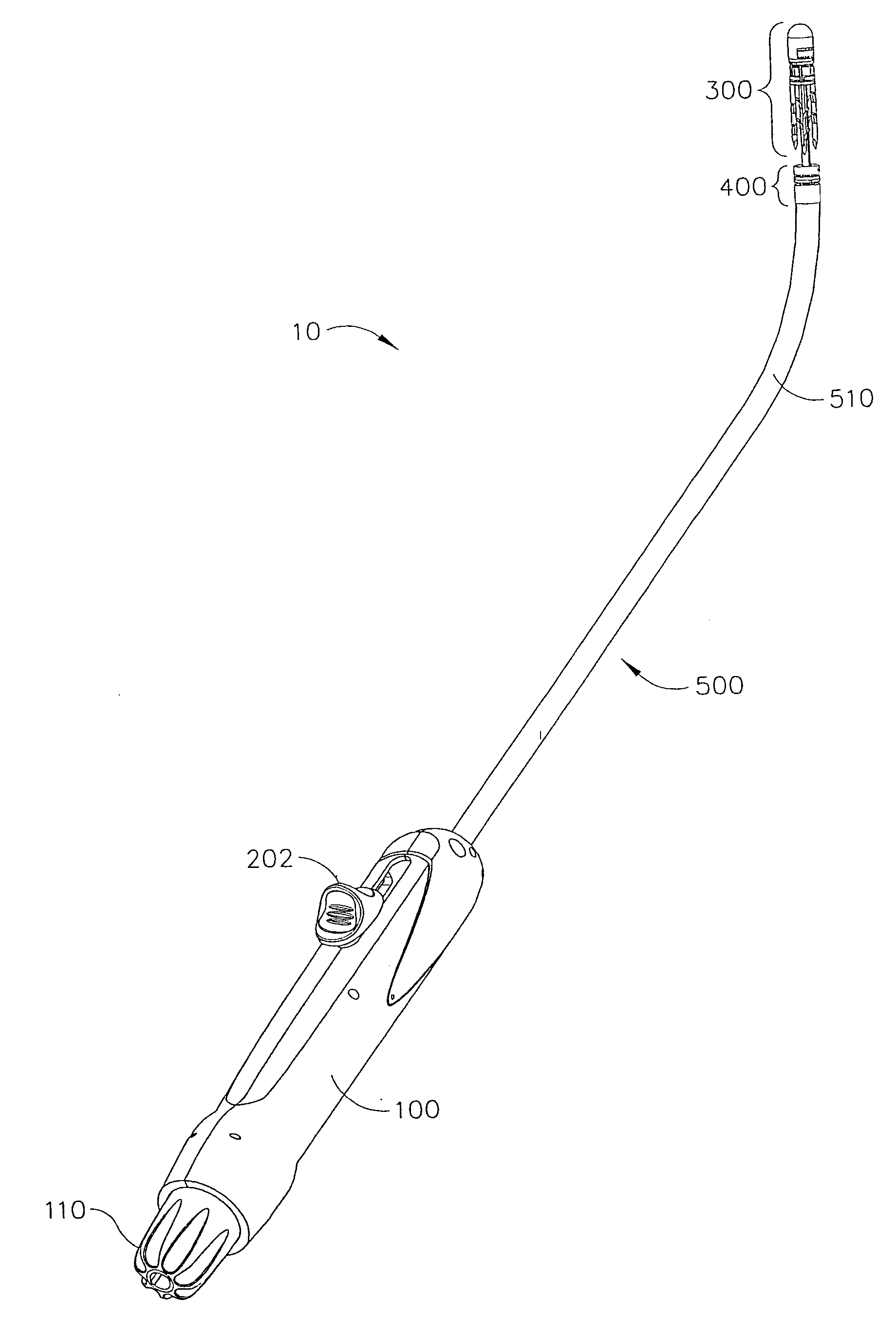
[0187]FIGS. 3-16 show an embodiment of an instrument 10 which may be used to perform an anastomosis procedure, for example, a procedure to effect anastomosis of a patient's bladder and urethra following a prostatectomy.
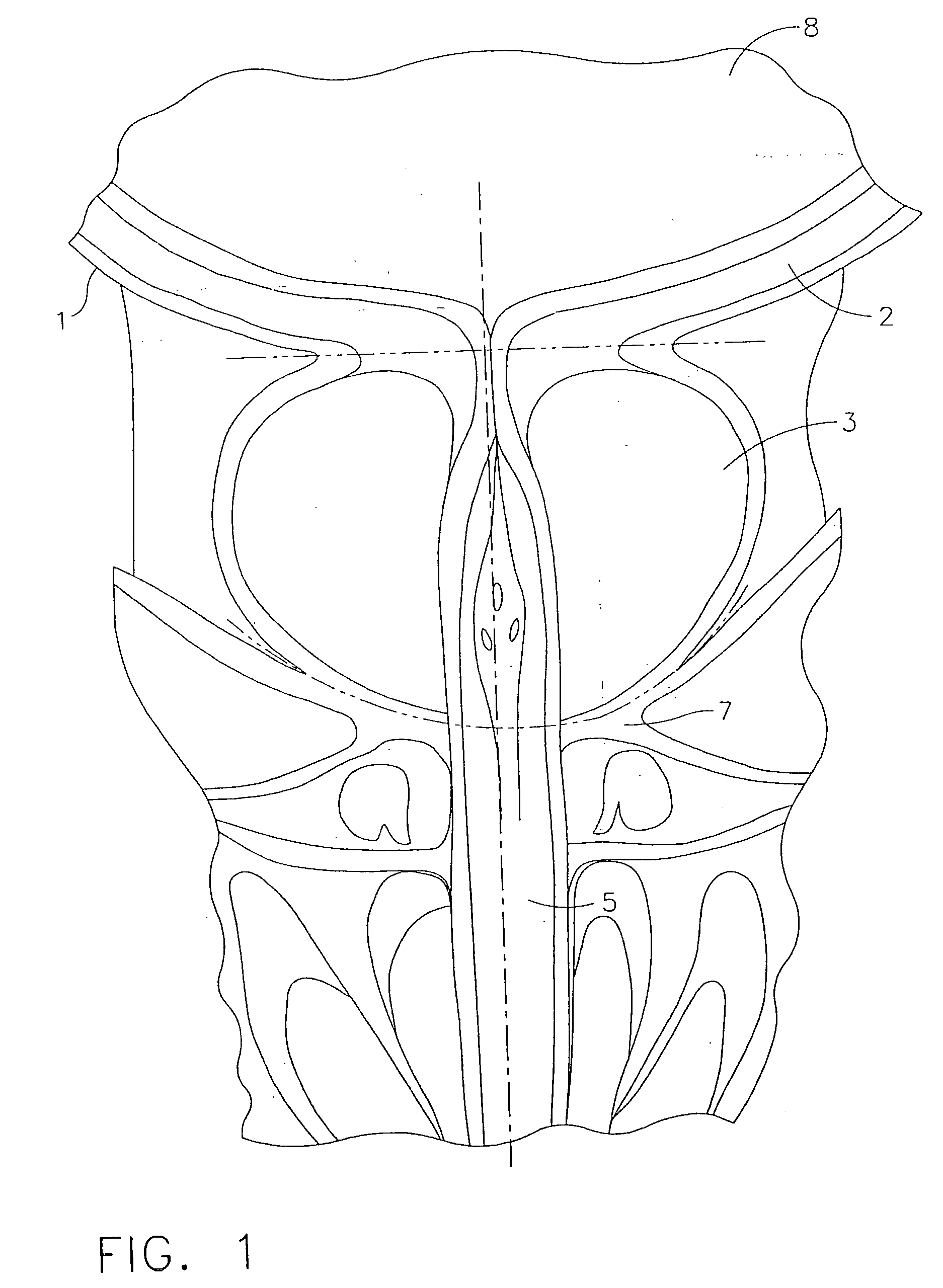
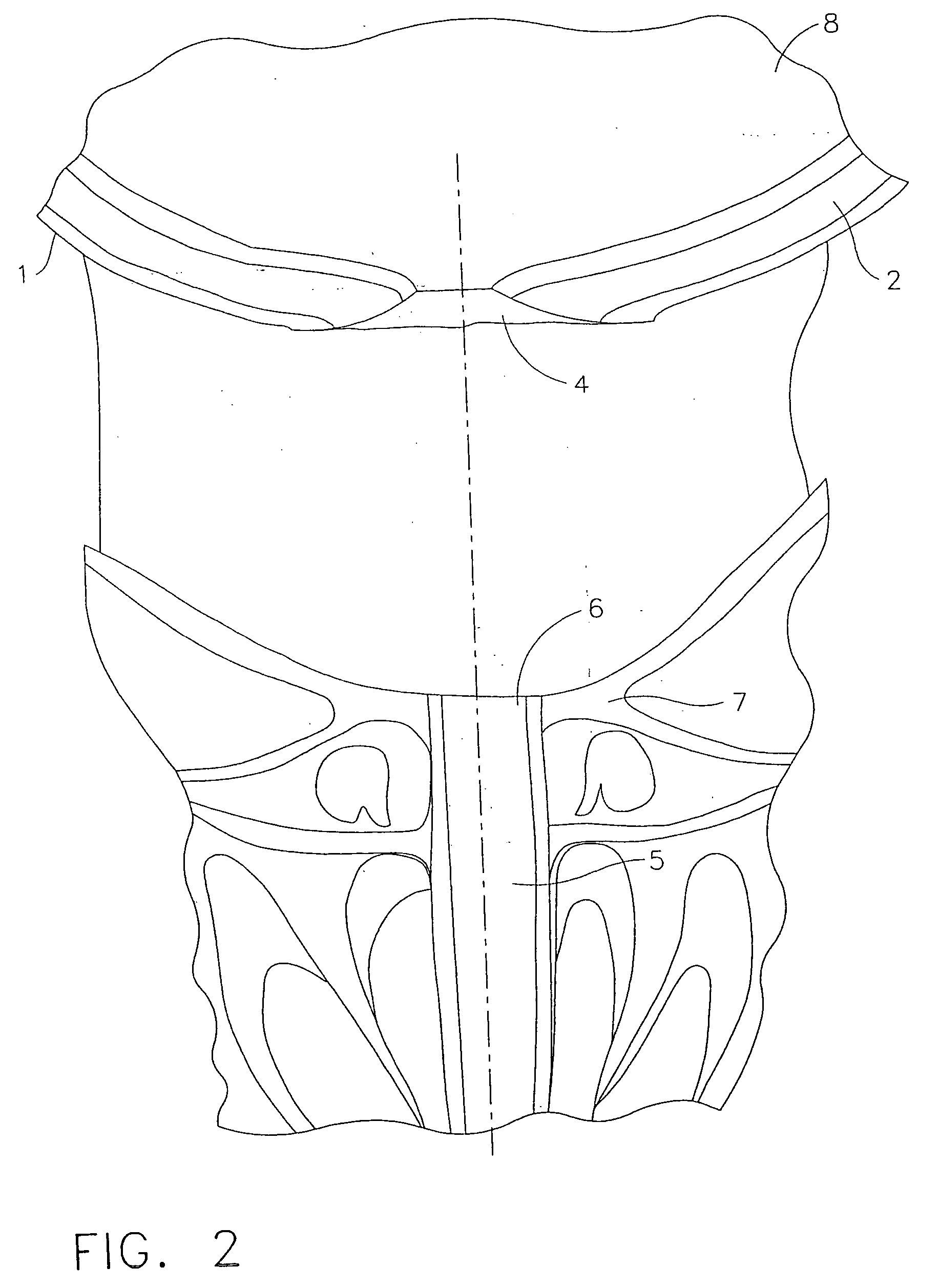
[0188] As shown configured for use in a retrograde manner in FIG. 3, one embodiment of the anastomotic applier instrument 10 in accordance with the invention may comprise an elongated tube assembly 500, a driver assembly 300 secured onto the distal end of the tube assembly 500, an optional positioner assembly 400 which may be used to bring the bladder wall and the pelvic floor tissues into close proximity or contact, and an actuator handle 100 for effecting opening of the positioner and driver assemblies and the driving and seating of anchors. In general, the instrument may be used for performing a vesico-urethral anastomosis after the prostate has been removed in a radical retropubic prostatectomy (see FIGS. 1 and 2). This connection is...
embodiment
Connecting Anchor Embodiment
[0363]FIG. 95 is a perspective view of another embodiment of an anastomotic instrument 2100 of the present invention, in its pre-deployment position, and FIG. 96 is a longitudinal cross-sectional view of the distal end of the instrument, also shown in its pre-deployment position. The instrument may comprise anchor driver assembly 2101, which may include outer driver assembly tube 2102, having distal end 2104, second anchor track collar 2105, anchor driver tube 2109 which distally terminates with anchor driver pins 2108, and inner driver assembly tube 2110 which distally terminates with first anchor track collar 2112. The present embodiment may further comprise positioner tube 2121, positioner 2122 affixed to the distal end of positioner tube 2121, rod 2124 and rod cap 2125. When the instrument is assembled and prepared for use, anchor driver assembly 2101 may be loaded with one or more anchor pairs, each pair comprising first anchor 700 with an attached l...
PUM
 Abstract
Description
Claims
Application Information