Blind slat structure

a technology of blind slats and slats, which is applied in the direction of doors/windows, curtains, constructions, etc., can solve the problems of inconvenient practical use, easy injury of hands of users, and conventional blind slat structures, so as to avoid uncomfortable abrasion, facilitate smoother and easer operation, and efficiently protect hands of users

Inactive Publication Date: 2005-12-15
CHING FENG BLINDS INC CO LTD
View PDF4 Cites 10 Cited by
  • Summary
  • Abstract
  • Description
  • Claims
  • Application Information

AI Technical Summary

Benefits of technology

[0004] It is, therefore, the primary purpose of the present invention to provide a blind slat structure, including a Venetian blind having rope ladders mounted between an upper and lower beams for a plurality of slats to be equidistantly abutted against for location thereby wherein a guide cord fixed inside the upper beam is extended downwards by the ends to sequentially pass through cord-passages holes disposed at the left/right sides of each slat thereof till both ends thereof coming out through the lower beam and stretched correspondingly inwards to the middle section at the bottom side of the lower beam to be collected together by a retaining body with a pulling section suspending downwards for a certain length there-from; thus, in operation, the slats of the Venetian blind thereof are simply collected or unfolded via the retaining body directly abutted against the lower beam to lift upwards or descend the lower beam along the guide cord, achieving an easer and effortless operation thereof.
[0005] It is, therefore, the second purpose of the present invention to provide a blind slat structure wherein,...

Problems solved by technology

There are some drawbacks to such conventional blind slat structure.
In case the pull cord 15 gets loose carelessly in the folding-up operation thereof, the weight of the lower beam 12 will quickly draw downwards the pull cord 15 and hands of a users can easily get hurt due to the abrasion against the pull cords 15 thereof, which is quite inconvenient in practical use.
When improperly tilted in angle or drawn to the wrong side, the pull cord 15 tends to get ja...

Method used


Image

  • Blind slat structure
  • Blind slat structure
  • Blind slat structure

Examples


Embodiment Construction

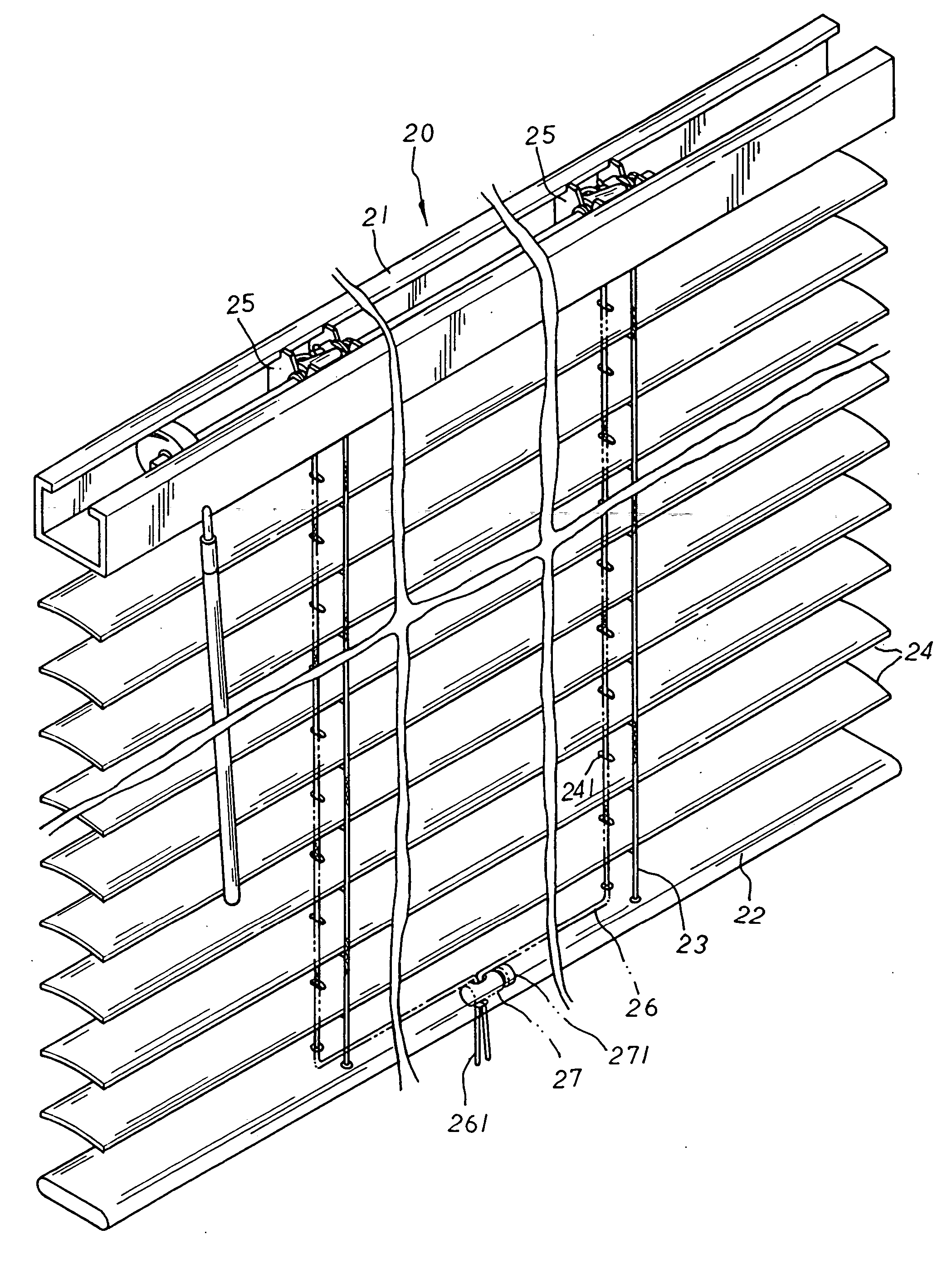
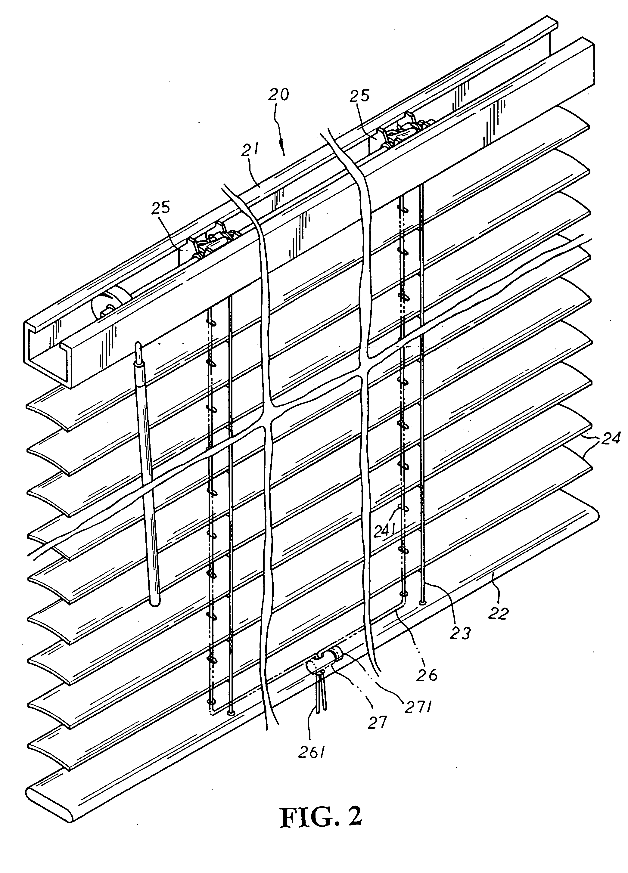
[0010] Please refer to FIGS. 2 to 4 inclusive. The present invention is related to a blind slat structure, including a Venetian blind 20 made up of rope ladders 23 mounted between an upper and lower beams 21, 22 for a plurality of slats 24 to be sequentially led there-through and equidistantly abutted against for location thereby. The upper ends of the rope ladders 23 are wound through and located at mounting seats 25, each having an adjustment roller, which are adapted at both inner lateral sides of the upper beam 21 therein to control the rotation of the slats 24 in different angles thereby. A guide cord 26 fixed inside the upper beam 21 at preset position relative to the two mounting seats 25 thereof is extended downwards by the ends to sequentially pass through cord-passages holes 241 disposed at the left / right sides of each slat 24 thereof from top to bottom till coming out through the lower beam 22 thereof. Both ends of the guide cord 26 are correspondingly stretched inwards t...


PUM


Abstract

A blind slat structure includes a Venetian blind having rope ladders mounted between an upper and lower beams for a plurality of slats to be sequentially led there-through and equidistantly abutted against for location thereby wherein the upper ends of the rope ladders are wound and located at mounting seats adapted at both inner lateral sides of the upper beam to control the rotation of the slats in different angles thereby, and a guide cord, fixed inside the upper beam at preset position relative to the mounting seats thereof, is extended downwards by the ends to sequentially pass through cord-passages holes disposed at the left/right sides of each slat thereof till both ends thereof coming out through the lower beam and stretched inwards to the middle section at the bottom side of the lower beam to be collected together by a retaining body with a pulling section suspending downwards for a certain length there-from. In operation, the slats of the Venetian blind thereof is simply collected or unfolded via the retaining body that, directly abutted against the lower beam, is easily slid upwards or downwards along the guide cord thereof with the lower beam synchronically moved up or down therewith, achieving an easier and effortless operation thereof so as to avoid the uncomfortable feeling of abrasion to hands caused by a conventional Venetian blind, and efficiently protecting the hands of a user as well as facilitating a smoother and easer operation thereof.

Description

BACKGROUND OF THE INVENTION [0001] The present invention is related to a blind slat structure, including a Venetian blind made up of rope ladders mounted between an upper and lower beams for a plurality of slats to be equidistantly abutted against for location thereby wherein a guide cord fixed inside the upper beam is extended downwards by the ends to sequentially pass through cord-passages holes disposed at the left / right sides of each slat thereof till both ends thereof coming out through the lower beam and stretched correspondingly inwards to the middle section at the bottom side of the lower beam to be collected together by a retaining body with a pulling section suspending downwards for a certain length there-from. In operation, the slats of the Venetian blind thereof are simply collected or unfolded via the retaining body that, directly abutted against the lower beam, is easily slid upwards or downwards along the guide cord with the lower beam synchronically moved up or down ...

Claims


Application Information

Patent Timeline
IPC IPC(8): E06B9/32E06B9/324E06B9/30E06B9/388A47H23/02
CPCE06B9/32E06B9/324E06B9/388
Inventor HSU, BEN
Owner CHING FENG BLINDS INC CO LTD
Why Eureka
Try Eureka