

LED sign with continuous illumination effect
- Summary
- Abstract
- Description
- Claims
- Application Information
AI Technical Summary
Benefits of technology
Problems solved by technology
Method used
Image

Examples
Embodiment Construction
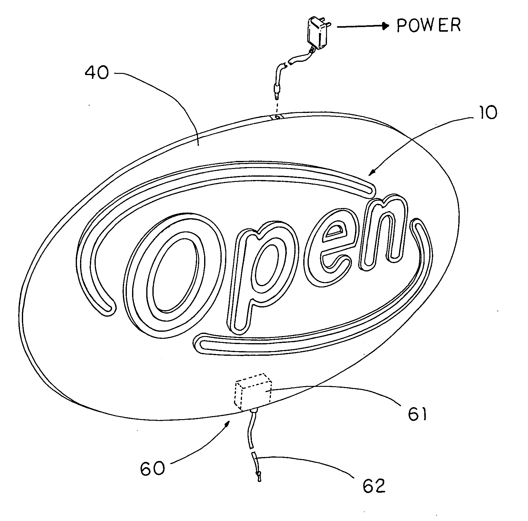
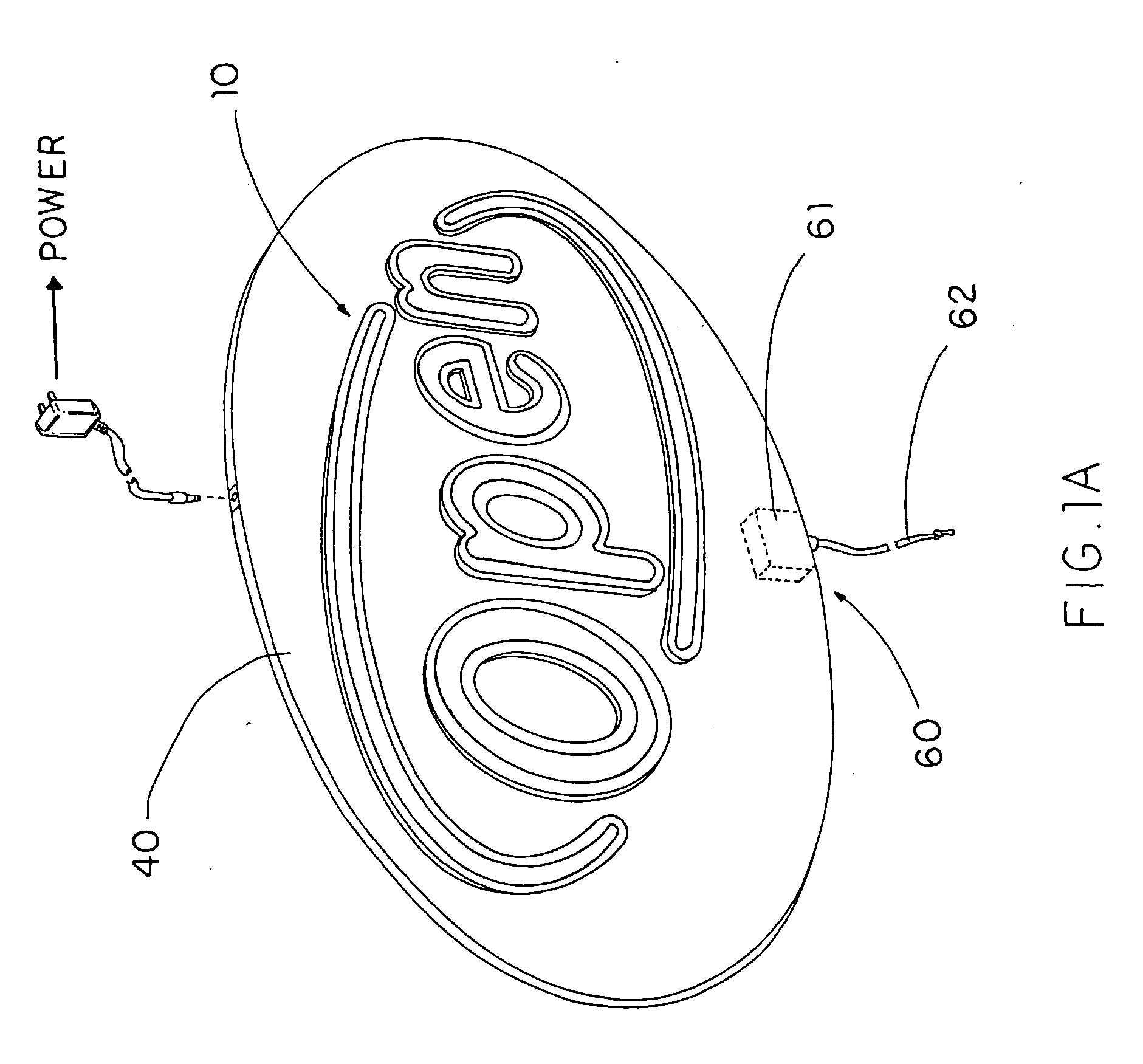
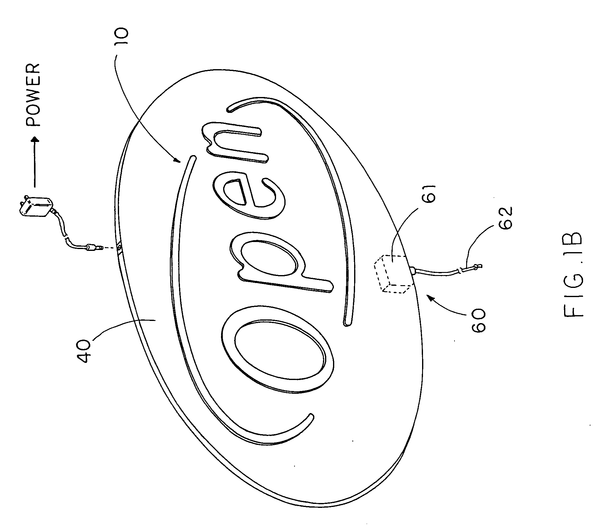
[0026] Referring to FIG. 1A, FIG. 1B and FIG. 2A, FIG. 2B of the drawings, a LED sign according to a preferred embodiment of the present invention is illustrated, in which the LED sign comprises a figure sign 10, at least one light guider 20, and a plurality of LED illuminators 30.
[0027] The figure sign 10 is shaped as forming a particular character having a predetermined light transmisivity and color. For example, the figure sign 10 may be embodied as a ‘O’ character in which it may be coated with a particular color for particular purpose, such as for use in a particular advertisement campaign.
[0028] The light guider 20 is shaped corresponding to the character sign 10, wherein it is overlappedly supported on a central portion of a front side of the light guider 20 and optically communicated with the illumination channel 21. Moreover, the light guider 20 further has a plurality of light cavities 23 for receiving the LED illuminators 30.
[0029] The plurality of LED illuminators 30 ...
PUM
 Abstract
Description
Claims
Application Information