Manufacturing method of a coil assembly

a manufacturing method and coil technology, applied in the manufacture of slip-rings, magnets, magnetic bodies, etc., can solve the problems of difficult to change the pitch of each of a plurality of coil members, and the length of straight portions cannot be easily adjusted, so as to achieve the effect of easy chang

Inactive Publication Date: 2006-01-12
MITSUBISHI ELECTRIC CORP
View PDF22 Cites 24 Cited by
  • Summary
  • Abstract
  • Description
  • Claims
  • Application Information

AI Technical Summary

Benefits of technology

[0007] An object of the present invention is to provide an improved manufacturing method of a coil member of a rotary electric machine which can easily adjust the pitch and the length of straight portions of the coil member.
[0008] Another object of the invention is to provide an improved manufacturing method of a coil assembly of a rotary electric machine which can easily adjust the pitch and the length of straight portions of each of coil members of the coil assembly.
[0009] A further object of the invention is to provide an improved manufacturing apparatus of a coil member of a rotary electric machine which can easily adjust the pitch and the length of straight portions of the coil member.
[0011] According to this manufacturing method of the coil member of the rotary electric machine, the prescribed dimensions L and p can be changed easily and hence a coil member can be manufactured while the length and the pitch of straight portions of the coil member are changed easily when necessary.
[0013] According to this manufacturing method of the coil assembly of the rotary electric machine, the prescribed dimensions L and p can be changed easily and hence a coil assembly can be manufactured while the length and the pitch of first and second portions of each coil member are changed when necessary.
[0015] According to this manufacturing apparatus for the coil member of the rotary electric machine, the prescribed dimensions L and p can be changed easily and hence a coil member can be manufactured while the length and the pitch of straight portions of the coil member are changed easily when necessary.

Problems solved by technology

Therefore, it is difficult to change the pitch of each of a plurality of coil members, that is, the interval between two adjoining straight portions.
To adjust the length of straight portions, it is necessary to prepare plural pairs of plate-like winding cores having different widths and replace one pair with another; the length of straight portions cannot be adjusted easily either.

Method used


Image

  • Manufacturing method of a coil assembly
  • Manufacturing method of a coil assembly
  • Manufacturing method of a coil assembly

Examples


embodiment 1

[0045] A first embodiment relating to the manufacturing method of a coil member 15 of a rotary electric machine according to the invention will be hereinafter described.

[0046] In the manufacturing method of a coil assembly 10 according to the invention, a winding step of forming coil members 15, a weaving step, a pressing step, a displacing step, and an inserting step are executed in this order. Since the weaving step and the following steps constitute a manufacturing method of a coil assembly 10 using coil members 15, firstly, the first embodiment relating to the manufacturing method of a coil member 15 according to the invention that is mainly the winding step of forming a coil member 15 will be described and then an embodiment relating to the manufacturing method of a coil assembly 10 using resulting coil members 15 will be described.

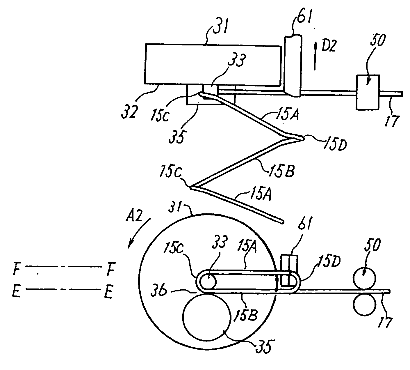
[0047] In the manufacturing method of the coil assembly 10, the first and second portions 15A, 15B are folded to have the parallel straight portio...

embodiment 2

[0074] Next, a description will be made of a second embodiment relating to the manufacturing method of a coil assembly 10 of a rotary electric machine that has a plurality of coil members 15. In the second embodiment, a coil assembly 10 is manufactured by using coil members 15 manufactured according to the first embodiment. In this manufacturing method of a coil assembly 10, a weaving step, a pressing step, a displacing step, and an inserting step are executed in this order.

[0075] In the second embodiment, after many coil members 15 shown in FIGS. 24(a) and 24(b) have been manufactured by the winding step, one coil member 15 is woven into another. The weaving step will be described below with reference to FIGS. 25(a) and 25(b) to FIGS. 30(a) and 30(b) in which FIGS. 25(a), 26(b), . . . , 30(a) are plan views and FIGS. 25(b), 26(b), . . . , 30(b) are front views.

[0076] FIGS. 25(a) and 25(b) show an initial state of the weaving step. In the weaving step, one coil member 151 is woven...

embodiment 3

[0101] A third embodiment relating to the manufacturing method of a coil assembly of a rotary electric machine according to the invention will be described below with reference to FIG. 35.

[0102] The third embodiment relates to a weaving method in which after completion of execution of the winding step on one coil member 15, another coil member 15 is woven into the one coil member 15 while being formed by winding the wire 17. In FIG. 35, components and portions having the same ones in the first or second embodiment are given the same reference symbols as the latter.

[0103] In FIG. 35, a coil member 151 that has been obtained by executing the winding step exists on the left side and another coil member 153 exists on the right side. FIG. 35 shows a state that the coil members 151 and 153 have been woven together over only 2.5 turns. The first one of the straight first portion 15A from the left of the coil member 153 is positioned above the third one of the straight second portion 15B ...


PUM

PropertyMeasurementUnit
lengthaaaaaaaaaa
dimensionaaaaaaaaaa
mass-productivityaaaaaaaaaa

Abstract

A manufacturing method includes a step of setting prescribed dimensions L and p, a wire feeding step of feeding a wire on a turning base surface by the dimension L, a turning step of turning the wire on the turning base surface to thereby form a first turning portion, a straight first portion, a second turning portion and a straight second portion, and a pushing step of pushing the straight first portion or the straight second portion so that it goes away from the turning base surface by the dimension p. A manufacturing apparatus that executes the above steps is also disclosed.

Description

BACKGROUND OF THE INVENTION [0001] 1. Field of the Invention [0002] The present invention relates to a manufacturing method of a coil member of a rotary electric machine such as a vehicular AC generator that is mounted on a car, a truck, or the like, a manufacturing method of a coil assembly that is an assembly of coil members each being the above one, and a manufacturing apparatus for the above coil member. [0003] 2. Description of the Related Art [0004] The present assignee proposed a technique for increasing the mass-productivity of the above-kind of coil member of a rotary electric machine and coil assembly in U.S. Pat. No. 6,376,961 (in particular, line 58 of column 11 to line 12 of column 12, and FIG. 8). In this related art technique, a coil assembly of a rotary electric machine has a plurality of coil combinations each being a combination of two coil members. Each coil member is manufactured by turning a wire continuously. This technique can provide higher mass-productivity ...

Claims


Application Information

Patent Timeline
Patent Type & Authority Applications(United States)
IPC IPC(8): H02K15/00H02K3/12H02K15/04
CPCH02K3/12H02K15/0478Y10T29/49011Y10T29/49071Y10T29/49073Y10T29/49009Y10T29/53143
Inventor HIROTA, YUTAKAHARADA, YOSHIHIROOOHASHI, ATSUSHI
Owner MITSUBISHI ELECTRIC CORP
Why Eureka
Try Eureka