End protector link for conveyor chain

a technology of conveyor chain and end protector, which is applied in the direction of conveyors, packaging, transportation and packaging, etc., can solve the problems of destroying the integrity of the chain, damage to the outermost extremities of the chain, and rubbing action will abrade or damage the heads of the ends of the pin, so as to prevent rubbing and damage

Active Publication Date: 2006-03-16
RAMSEY PRODS CORP
View PDF7 Cites 17 Cited by
  • Summary
  • Abstract
  • Description
  • Claims
  • Application Information

AI Technical Summary

Benefits of technology

[0003] Therefore, it is an object of the invention to provide an end protector li

Problems solved by technology

Eventually this rubbing action will abrade or damage the heads on the ends of these pins.
Such wear may also damage links at the outermost extremity of the chain.
If the damage or wear to pin heads or links is sufficient the pins and/or links may come out of the chain assembly, effectively destroying the integrity of the chain and damaging the con

Method used


Image

  • End protector link for conveyor chain
  • End protector link for conveyor chain
  • End protector link for conveyor chain

Examples


Embodiment Construction

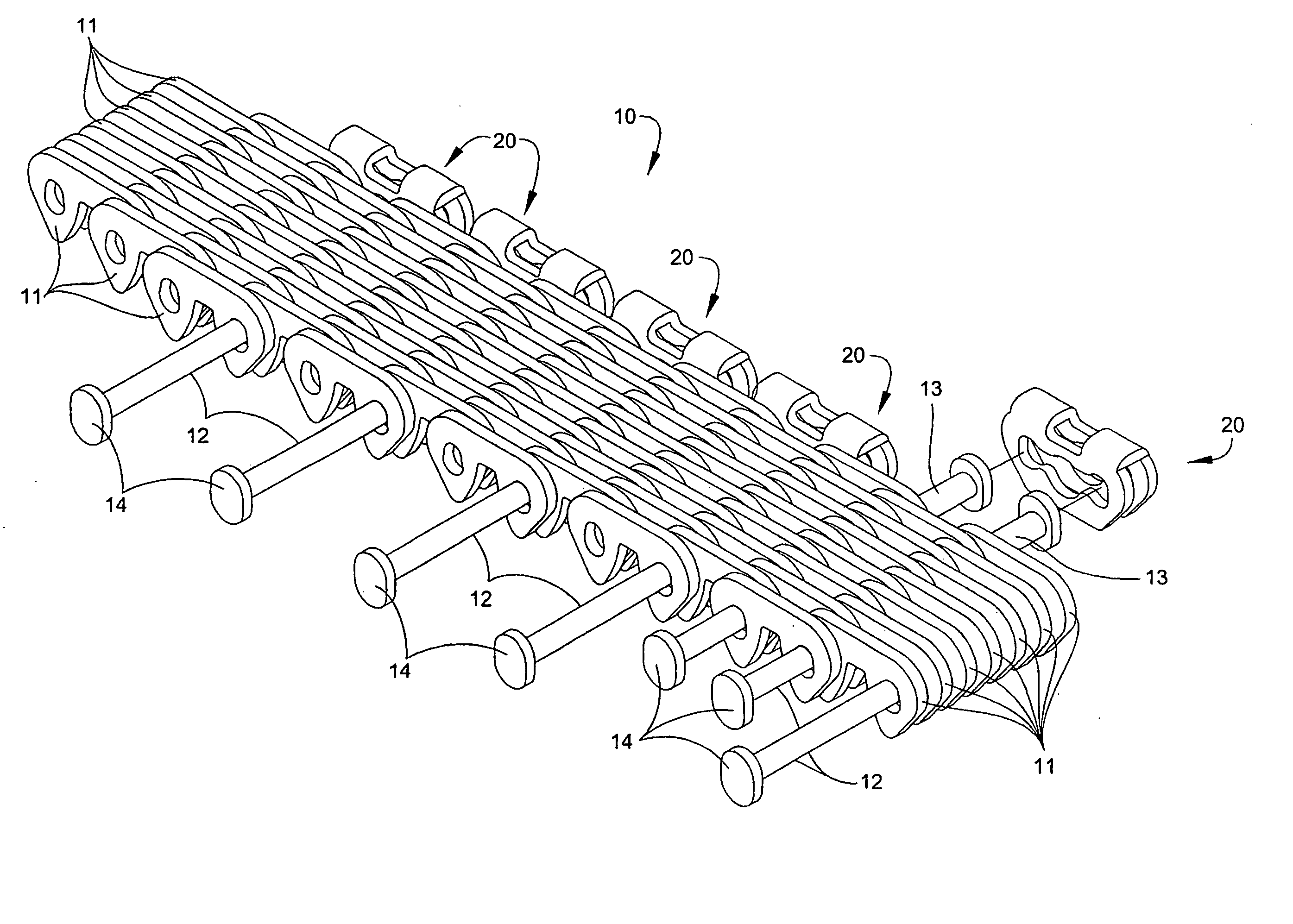
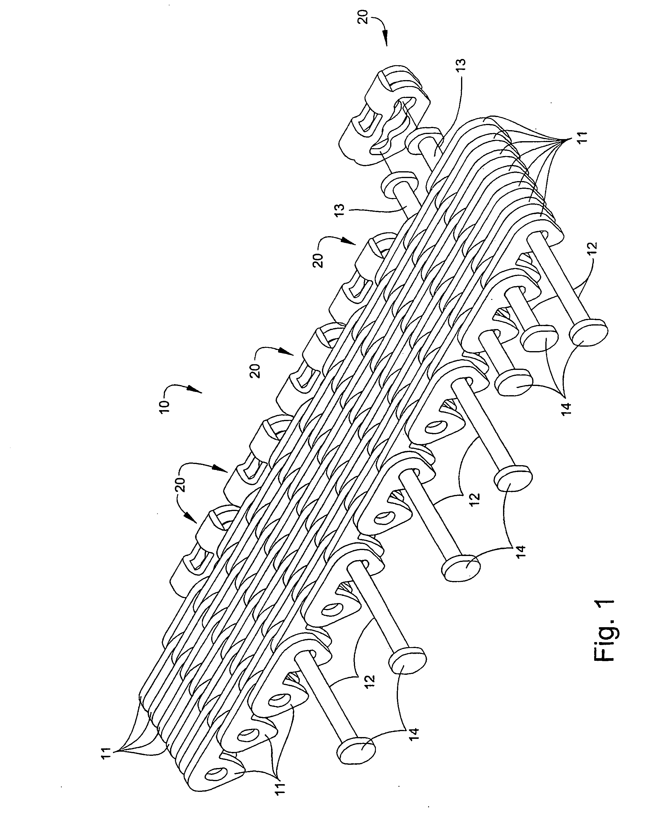
[0053] Referring now specifically to the drawings, a conveyor chain according to an embodiment of the present invention is illustrated in FIG. 1 and shown generally at reference numeral 10. The chain 10 is formed of a multitude of interconnected links 11 threaded onto link pins 12, as shown. One typical manner of assembling the chain 10 is by using pins 12 with a head 13 on only one end, threading the links in the required sequence and arrangement onto the shaft of the pins over the headless end, and utilizing the head to retain the links. After the full width of the chain 10 is assembled, a head 14 is applied to the previously headless end, for example, by spin riveting. The pins 12 are typically elliptical or ovoid in cross-section to facilitate movement within the links 11.

[0054] As noted above, chains such as chain 10 are frequently used in the transport and conveying of materials either as a conveying surface, or as the means for moving other containers in which a conveyed mat...


PUM


Abstract

An end protector link (60) captures and retains first and second elongate link pins of a multi-link conveyor chain, and includes an outer wall (41) defining a protective bearing surface, a spacer wall (62) carried by the outer wall, and an inner wall (63) carried by the spacer wall in spaced-apart relation to the outer wall and having a retainer aperture (75) for capturing and retaining respective enlarged heads (13) of the first and second link pins (12) between facing surfaces of the outer wall and the inner wall. The protective bearing surface of the outer wall is adapted for being engaged by wearing surfaces past which the conveyor moves to protect the enlarged heads (13) of the link pins to exposure to the wearing surfaces.

Description

TECHNICAL FIELD AND BACKGROUND OF THE INVENTION [0001] This invention relates to an end protector link for chains, such as silent or inverted tooth chains. Such chains are frequently used in transporting and conveying materials either as a conveying surface or as the means for moving other containers in which a conveyed material is placed. In such applications, the chain is frequently operated in a path that is bounded by lateral guides, wear strips, or other objects located on either or both sides of the chain. As the chain moves along this path, the ends of the pins projecting from the sides of the chain and the link on the outermost extremity of the chain may rub against the lateral guides, wear strips, or other objects. Eventually this rubbing action will abrade or damage the heads on the ends of these pins. Such wear may also damage links at the outermost extremity of the chain. If the damage or wear to pin heads or links is sufficient the pins and / or links may come out of the ...

Claims


Application Information

Patent Timeline
IPC IPC(8): B65G17/06B65G17/08B65G17/30B65G17/40
CPCB65G17/08B65G17/30B65G2207/12B65G2201/0235B65G17/40
Inventor HALL, WILLIAMC
Owner RAMSEY PRODS CORP
Why Eureka
Try Eureka