

Distractable body augmenter capable of being planted through a pedicle for vertebral body reconstruction
a technology of augmentation and vertebrae, which is applied in the field of attractive body augmentation capable of being planted through a pedicle for vertebral body reconstruction, can solve the problems of 20% implant failure, limited conservative treatment, and surgery itself a suffering of elder patients, so as to maintain or restore the normal position and size of the vertebra
- Summary
- Abstract
- Description
- Claims
- Application Information
AI Technical Summary
Benefits of technology
Problems solved by technology
Method used
Image

Examples
first embodiment
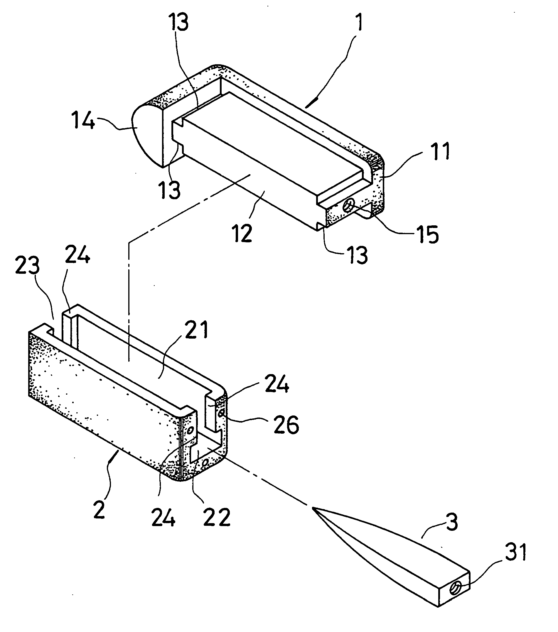
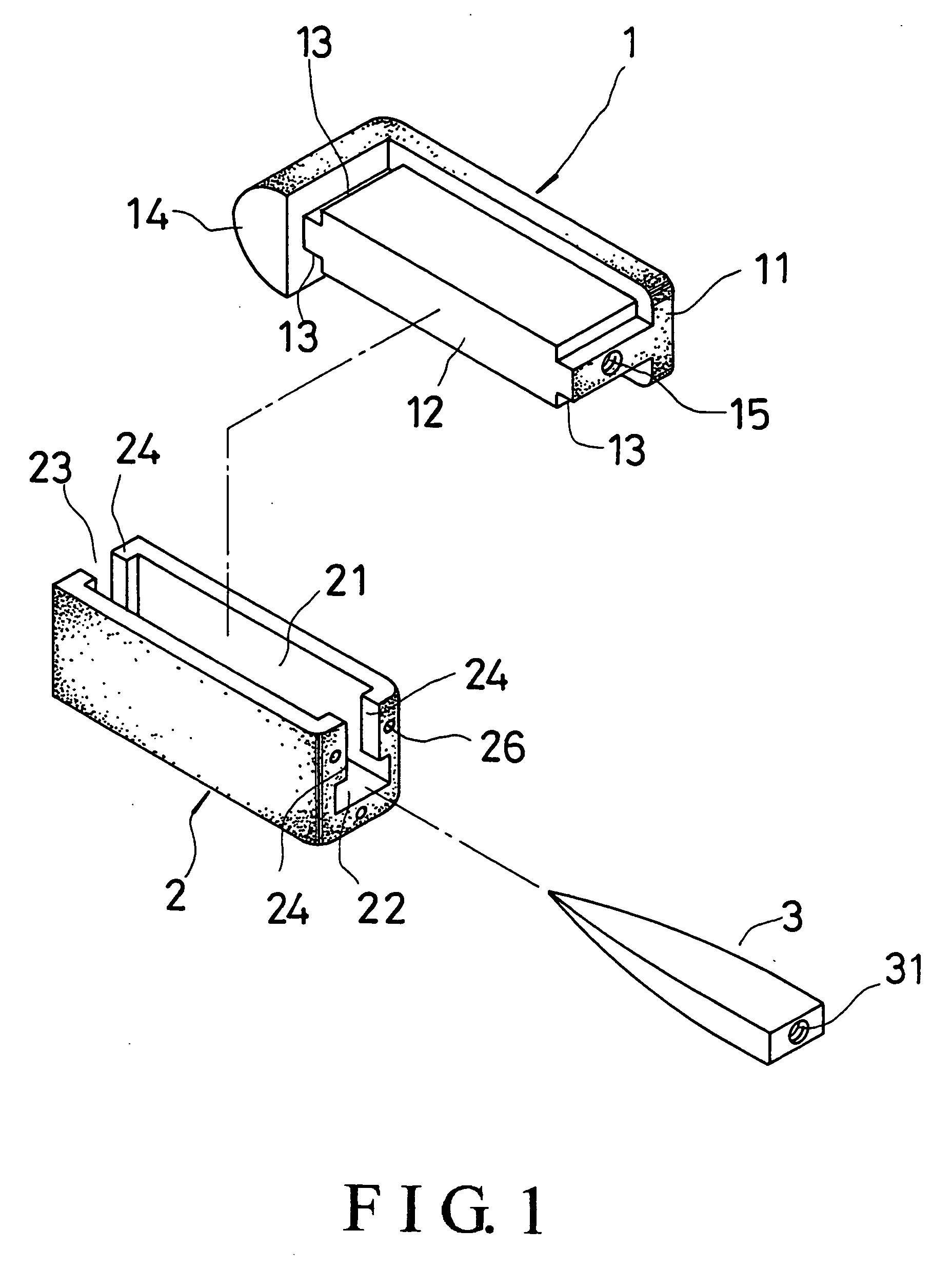
[0016] Referring to FIG. 1, a distractable body augmenter for vertebral body reconstruction in the present invention includes an upper planted block 1, a lower planted block 2, and a wedge-shaped bar 3.
[0017] Both the upper and the lower planted blocks 1 and 2 have rough surfaces with small bumps all over. The upper planted block 1 has an uppermost portion 11, an insertion portion 12 projecting down from a lower side of the uppermost portion 11, and a base 14 joined to a rear end of the insertion portion 12. The insertion portion 12 has longitudinal fitting trenches 13 on two sides of front end and rear end thereof, and a screw hole 15 on the front end. The base 14 has a convexly curved outer side.
[0018] The lower planted block 2 has two lengthways extending lateral portions 24, a holding cavity 21 between the lateral portions 24, an inverted T-shaped gap 22 at a front end thereof, and an U-shaped gap 23 at a rear end; the gaps 22 and 23 communicate with the holding cavity 21, and ...
second embodiment
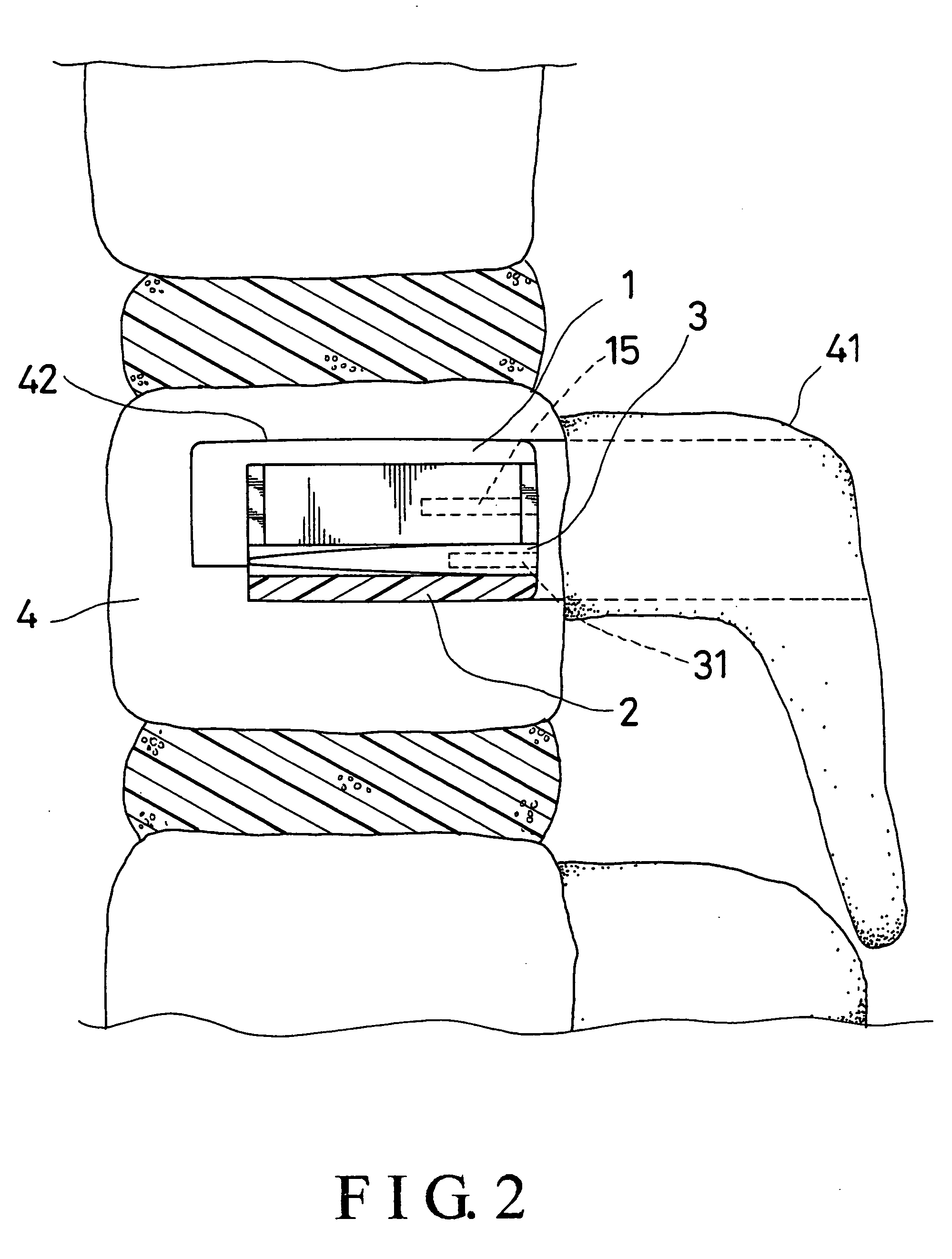
[0022] The dimension of the distractable body augmenter is decided according to the vertical cross-section and the height of the pedicle 41 of the vertebra 4; the vertical cross-section of the pedicle 41 is close to a rectangle, and somewhat oval, and the distance from an upper end to a lower end of the pedicle 41 is larger than that from a rear end to a front end; the ratio of the height of pedicle 41 to the height of the vertebra 4 is between 0.5 and 0.6. Therefore, the augmenter can be made with a size near to the pedicle 41 so that at least 50% to 60% of the vertebra 4 is reconstructed. Consequently, 70% to 80% of the vertebra 4 will be reconstructed when the augmenter is combined with the rest of the vertebra 4. Furthermore, the height of the distractable body augmenter will be changed up to 30% by means of changing the thickness of the wedge-shaped bar 3, and in turns, the vertebra 4 can nearly recover the original size, which it had before the fracture. Therefore, with the he...
third embodiment
[0023] Referring to FIG. 6, which is an exploded perspective view of an augmenter for vertebral body reconstruction, wedge-shaped bar 3 is further formed with a downwards projecting extension portion 32 at a front end thereof while several holes 26 are formed on the front end of the lower insertion block 2. Thus, another tool can be connected with the holes 26 to help the augmenter planted in the vertebra 4, and the front ends of the upper and the lower planted blocks 1 and 2 will be co-planar in the vertebra 4, as shown in FIG. 7.
[0024] From the above description, it can be easily understood that the distractable body augmenter of the present invention has advantages as followings:
1. The distractable body augmenter is planted in a collapsed vertebra followings:
[0025] 1. The distractable body augmenter is planted in a collapsed vertebra via the pedicle of a vertebra instead of via the thoracic or abdominal cavity of the patient therefore the operation is relatively safe, and mech...
PUM
 Abstract
Description
Claims
Application Information