Cable bracket for a bicycle

Inactive Publication Date: 2006-05-18
CHEN MENG HUNG +1
View PDF10 Cites 10 Cited by
  • Summary
  • Abstract
  • Description
  • Claims
  • Application Information

AI Technical Summary

Benefits of technology

[0010] The main objective of the invention is to provide a cable bracket that can

Problems solved by technology

Thus, braking efficiency of the bicycle is reduced and this may lead to injury or death, especially for very young or old riders that may not have sufficient s

Method used


Image

  • Cable bracket for a bicycle
  • Cable bracket for a bicycle
  • Cable bracket for a bicycle

Examples


Embodiment Construction

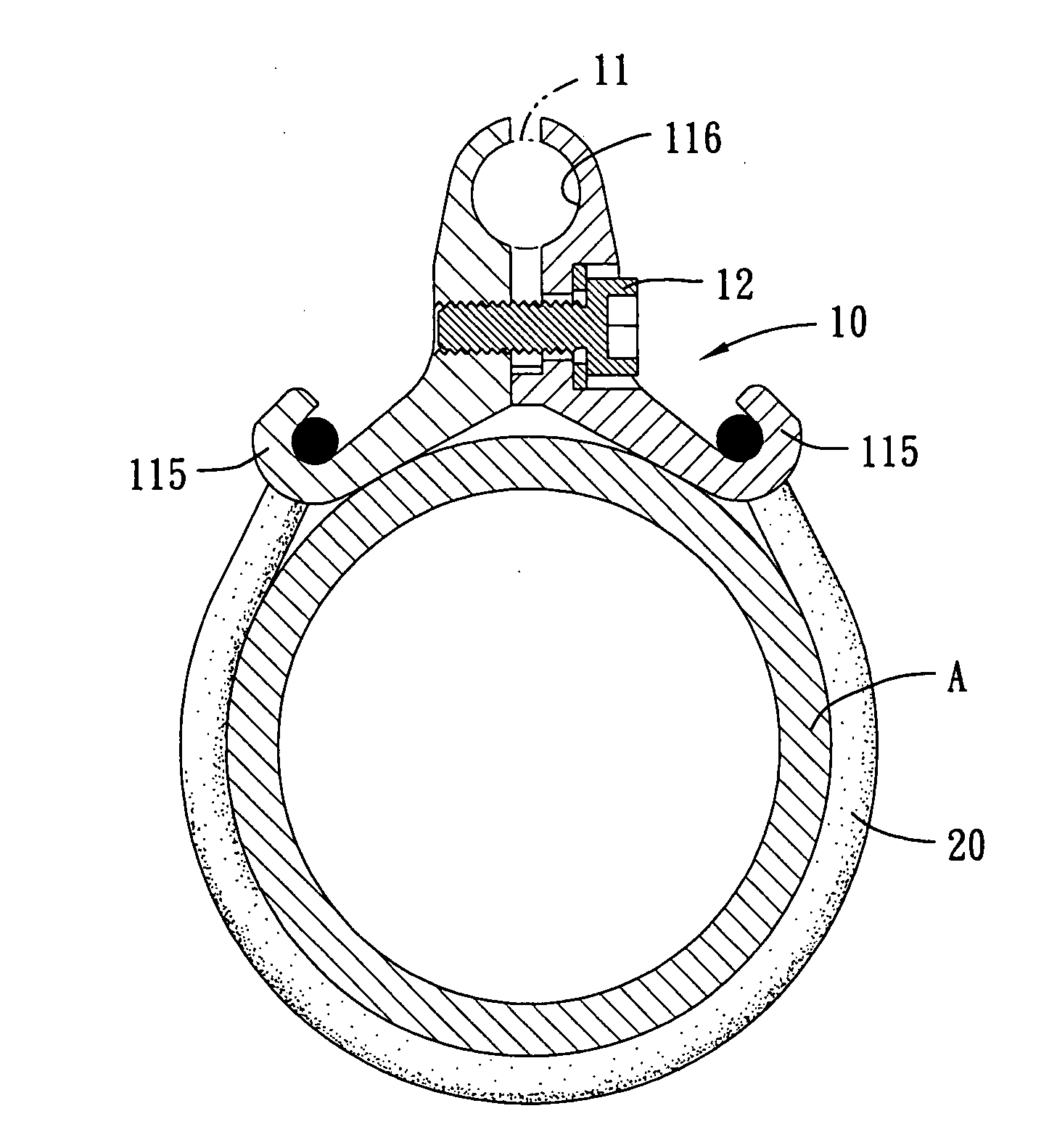
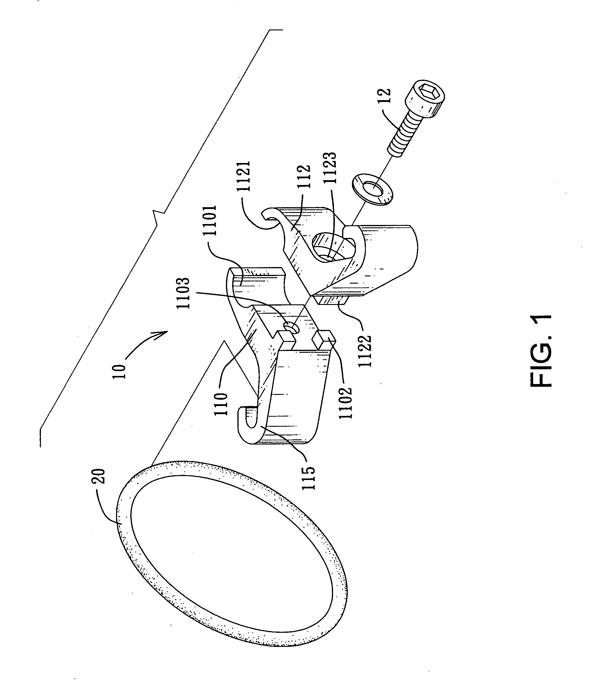
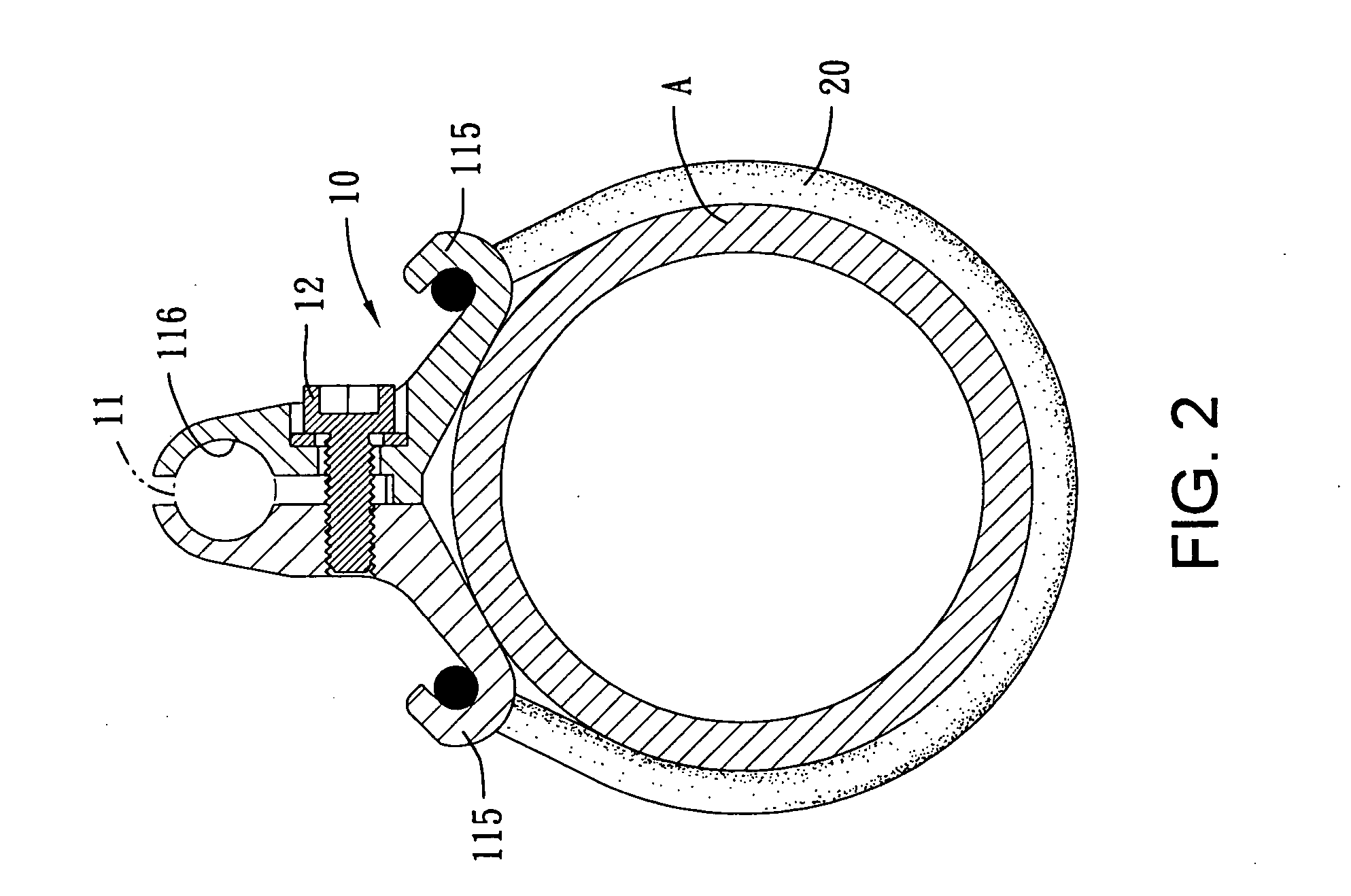
[0018] A cable bracket for a bicycle in accordance with the present invention comprises a frame and an optional resilient fastener. The frame is preferably Y-shaped and has a looped end and two branched ends. The looped end has a cable recess for holding at least one cable. Each branched end has a hook for retaining the resilient fastener. When the two branched ends embrace a tube of the bicycle at a proper position, the resilient fastener has two ends secured on the hook to make the frame attach on the tube firmly. Thereby, the cable bracket is detachably mounted on the tube. Moreover, the looped end only keeps the cable within the cable recess and does not constrict the cable so that the cable is kept in its original straight form without deformation and disturbance in operation.

[0019] With reference to FIGS. 1, 2 and 3, a preferred embodiment of the cable bracket for a bicycle comprises a body (10) and a resilient fastener (20).

[0020] The body (10) is Y-shaped and composed of t...


PUM


Abstract

A cable bracket for a bicycle has a frame and a resilient fastener. The frame is preferably Y-shaped and has a body with a looped end and two branched ends. The looped end has a cable recess for holding at least one cable. Each branched end has a hook for receiving the resilient fastener. When the two branched ends embrace a tube of the bicycle at a proper position, the resilient fastener has two ends secured on the hooks to make the frame attach on the tube firmly. Thereby, the cable bracket is detachably mounted on the tube. Moreover, the looped end only keeps the cable within the cable recess and does not constrict the cable so that the cable is kept in its original form without deformation or disturbance in operation.

Description

BACKGROUND OF THE INVENTION [0001] 1. Field of the Invention [0002] The present invention relates to a cable bracket for a bicycle, and more particularly a cable bracket that can be detached conveniently. [0003] 2. Description of Related Art [0004] To avoid brake cables or gear cables on a bicycle swinging when the bicycle is being ridden, bicycle manufacturers usually tie the cables onto the frame of the bicycle. With reference to FIG. 6, a conventional device for tying cables on the bicycle is a strip (50) such as cable pull-tie. The strip (50) has an elongated body with a toothed inner face and two ends. One end of the strip (50) has a latch head (52) and the other end of the strip is a tapered tongue (51). When the strip (50) is used to tie a cable (40) to on a fork (A) of the bicycle, the elongated body surrounds the cable (40) and the fork (A) together. Then, the tongue (51) penetrates through the latch head (52) and is pulled out to fasten the cable (40) on the fork (A), wher...

Claims


Application Information

Patent Timeline
IPC IPC(8): F16L3/08
CPCF16L3/127B62J11/13
Inventor CHEN, MENG-HUNGLEE, JIN-LONG
Owner CHEN MENG HUNG
Why Eureka
Try Eureka