Resistance adjusting apparatus with wind resistance and magnetic resistance

a technology magnetic resistance, which is applied in the direction of sport apparatus, gymnastic exercise, cardiovascular exercise devices, etc., can solve the problems of increased replacement cost difficult detachment of resistance adjusting apparatus from frame, and magnetic block location in magnetic wheel, etc., to reduce replacement cost and facilitate repair and replacement.

Active Publication Date: 2019-08-22
WU MU CHUAN
View PDF0 Cites 6 Cited by
  • Summary
  • Abstract
  • Description
  • Claims
  • Application Information

AI Technical Summary

Benefits of technology

[0007]The objective of the invention is to provide a resistance adjusting apparatus with wind resistance and magnetic resistance to facilitate ease in repair and replacement, and reduce the replacement cost.

Problems solved by technology

The resistance adjusting apparatus is hard to detach from the frame.
When the wind resistance plates are used after a long time and are damaged or broken, the outer wheel has to change to a new one.
The replacement cost of the resistance adjusting apparatus is increased.
In addition, the magnetic blocks are located in the magnetic wheel and are hard to repair and replace.

Method used


Image

  • Resistance adjusting apparatus with wind resistance and magnetic resistance
  • Resistance adjusting apparatus with wind resistance and magnetic resistance
  • Resistance adjusting apparatus with wind resistance and magnetic resistance

Examples


first embodiment

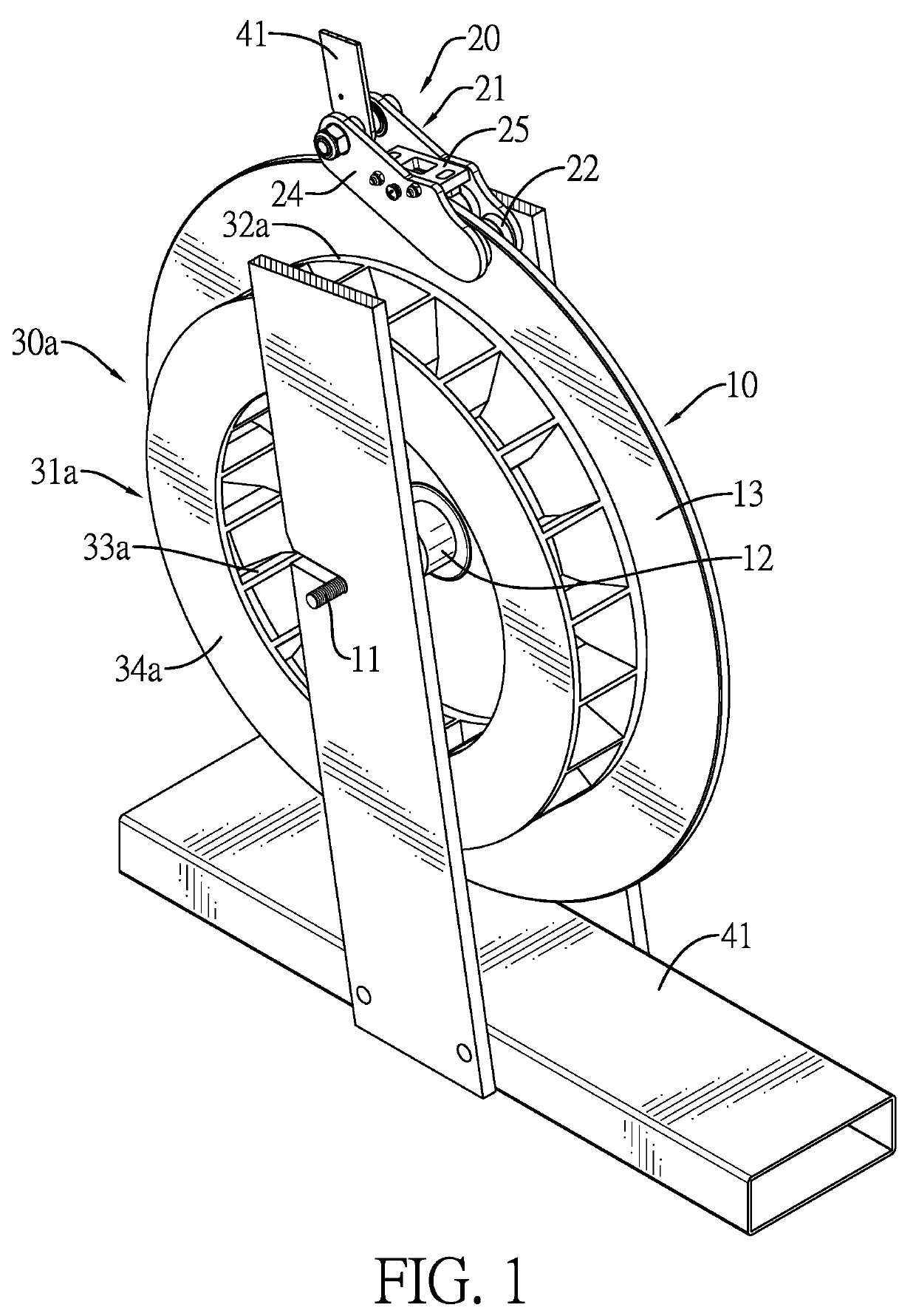
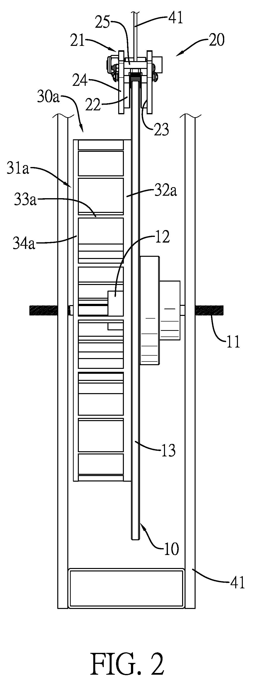
[0019]With reference to FIGS. 1 and 2, a resistance adjusting apparatus with wind resistance and magnetic resistance in accordance with the present invention is disposed on a frame 41, and comprises a rotating member 10, a magnetic resistance member 20, and a wind resistance member 30a.

[0020]The rotating member 10 has an axle 11, an assembly seat 12, and a magnetic wheel 13. The axle 11 is rotatably disposed on and inserted through the frame 11. The assembly seat 12 is fixedly disposed on the axle 11. The magnetic wheel 13 is detachably disposed on the assembly seat 12 and has an outer surface.

[0021]The magnetic resistance member 20 is swingably disposed on the frame 41, is located out of the magnetic wheel 13, and has an adjusting seat 21 and multiple magnetic elements 22. The adjusting seat 21 is swingably disposed on the frame 41 and has an inner space 23 formed in the adjusting seat 21. The magnetic wheel 13 is inserted into the inner space 23 of the adjusting seat 21. The magn...

second embodiment

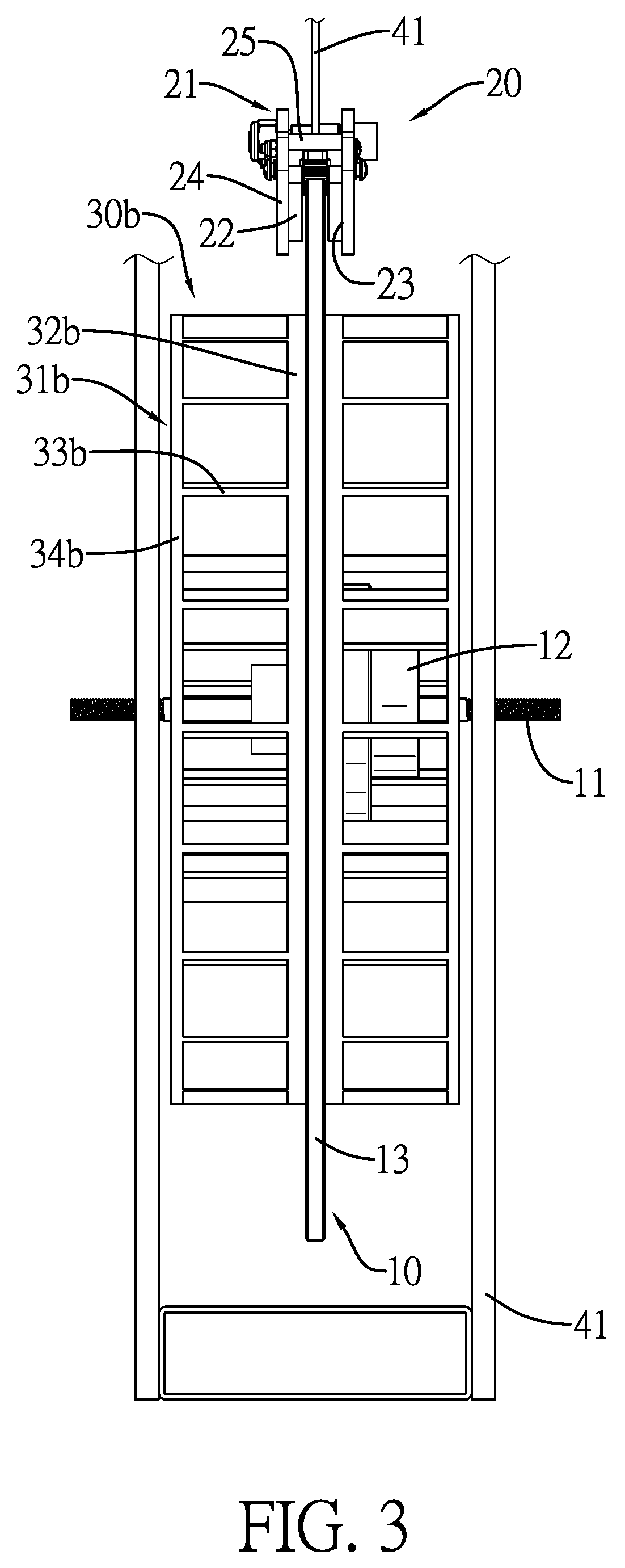
[0023]With reference to FIG. 3, in the second embodiment, the wind resistance member 30b has two turbines 31b. The two turbines 31b are respectively disposed on the two sides of the magnetic wheel 13. Each turbine 31b has a base 32b, multiple wings 33b, and a pressurized plate 34b. The base 32b is disposed on one of the two sides of the magnetic wheel 13 by screws. The wings 33b are annularly disposed on the base 32b at spaced intervals. The pressurized plate 34b is disposed on the wings 33b and is opposite to the base 32b.

third embodiment

[0024]With reference to FIGS. 4 and 5, in the third embodiment, the wind resistance member 30c has a fan 35c. The fan 35c is disposed on one of the two sides of the magnetic wheel 13 and has multiple wings 36c. The wings 36c are annularly disposed on the magnetic wheel 13 at spaced intervals by screws.


PUM


Abstract

A resistance adjusting apparatus is disposed on a frame and has a rotating member, a magnetic resistance member, and a wind resistance member. The rotating member has an axle rotatably disposed on the frame, an assembly seat fixedly disposed on the axle, and a magnetic wheel detachably disposed on the assembly seat. The magnetic resistance member is disposed on the frame, is located out of the magnetic wheel, and has an adjusting seat disposed on the frame and multiple magnetic elements. The magnetic wheel is inserted into an inner space of the adjusting seat. The magnetic elements are disposed in the adjusting seat and are located in the inner space of the adjusting seat. The wind resistance member is detachably disposed on an outer surface of the magnetic wheel. The wind resistance member and the magnetic resistance member are independent and can be detached individually.

Description

BACKGROUND OF THE INVENTION1. Field of the Invention[0001]The invention relates to a resistance adjusting apparatus, and more particularly to a resistance adjusting apparatus with wind resistance and magnetic resistance that is easy to assemble and repair.2. Description of Related Art[0002]As the awareness for exercise and fitness becomes more and more popular, fitness equipment has been developing in different types. For convenience of indoor exercise, an exercise bike or a rowing machine becomes popular fitness equipment. Furthermore, the fitness equipment has two kinds of resistance sources for increasing the training effect.[0003]Take the exercise bike for example. The exercise bike has a frame, a pedal assembly, a resistance adjusting apparatus, and a chain. The pedal assembly is mounted on the frame. The resistance adjusting apparatus is rotatably mounted on the frame and has an axle, an outer wheel, multiple wind resistance plates, a magnetic wheel, and multiple magnetic bloc...

Claims


Application Information

Patent Timeline
Patent Type & Authority Applications(United States)
IPC IPC(8): A63B21/00A63B21/008A63B22/06A63B21/22A63B23/035
CPCA63B21/00076A63B21/0088A63B21/00192A63B22/0605A63B21/22A63B21/4034A63B23/03583A63B21/4035
Inventor WU, MU-CHUAN
Owner WU MU CHUAN
Why Eureka
Try Eureka