Mainframe structure

a mainframe and computer technology, applied in the direction of electrical apparatus casings/cabinets/drawers, instruments, cooling/ventilation/heating modifications, etc., can solve the problems of complicated detach procedure and high labor and cost of application of advanced electronic devices, so as to simplify the detach procedure and avoid sticking

Inactive Publication Date: 2012-07-05
DATAVAN INT
View PDF2 Cites 7 Cited by
  • Summary
  • Abstract
  • Description
  • Claims
  • Application Information

AI Technical Summary

Benefits of technology

[0010]It is still another object of the present invention to provide a mainframe structure, wherein the circuit module consists of a main circuit board, a functional circuit board and a display circuit board; the main circuit board has its backwardly extending at least one first electrical connector and at least one second electrical connector respectively electrically connected to at least one first connection port of the functional circuit board and at least one second connection port of the display circuit board. Thus, when the user operates the handles to detach the cover, the applied force is evenly transferred to the stop members to force the main circuit board and the cover forwardly away from the housing without tilting, avoiding sticking and simplifying the detaching procedure.
[0011]It is still another object of the present invention to provide a mainframe structure, wherein the cover is a metal cover member comprising a plurality of radiation fins located on the front side thereof and a plurality of contact portions located on the back side thereof and respectively kept in contact with respective chips at the front side of the main circuit board for quick transfer of waste heat from the chips to the radiation fins for dissipation into the outside open air. Thus, no extra heat sink or cooler means is necessary for dissipating waste heat from the chips of the main circuit board, simplifying the installation procedure of the mainframe structure and saving much heat sink installation space.
[0012]It is still another object of the present invention to provide a mainframe structure, which is so arranged that when the user is going to detach the cover after the mainframe structure having been operating for a certain period of time, the user can loosen the cover mounting thumbscrews with one hand and then bias the handles with the two hands against the stop members to force the cover and the main circuit board forwardly away from the housing without any tools or direct hand contact with the hot cover, preventing scald injury.

Problems solved by technology

The application of these advanced electronic devices saves much labor and cost.
Because the cover panel A2 is fastened to the housing A over the opening A1 by screws and the circuit board B is affixed to the accommodation chamber A0 inside the housing A, a hand tool is necessary when detaching the cover panel A2 or the circuit board B. Without a suitable hand tool, a person cannot detach the cover panel A2 and the circuit board B. Further, because the cover panel A2 and the circuit board B are disposed at different locations, the detaching procedure is complicated, requiring much labor and time.

Method used


Image

  • Mainframe structure
  • Mainframe structure
  • Mainframe structure

Examples


Embodiment Construction

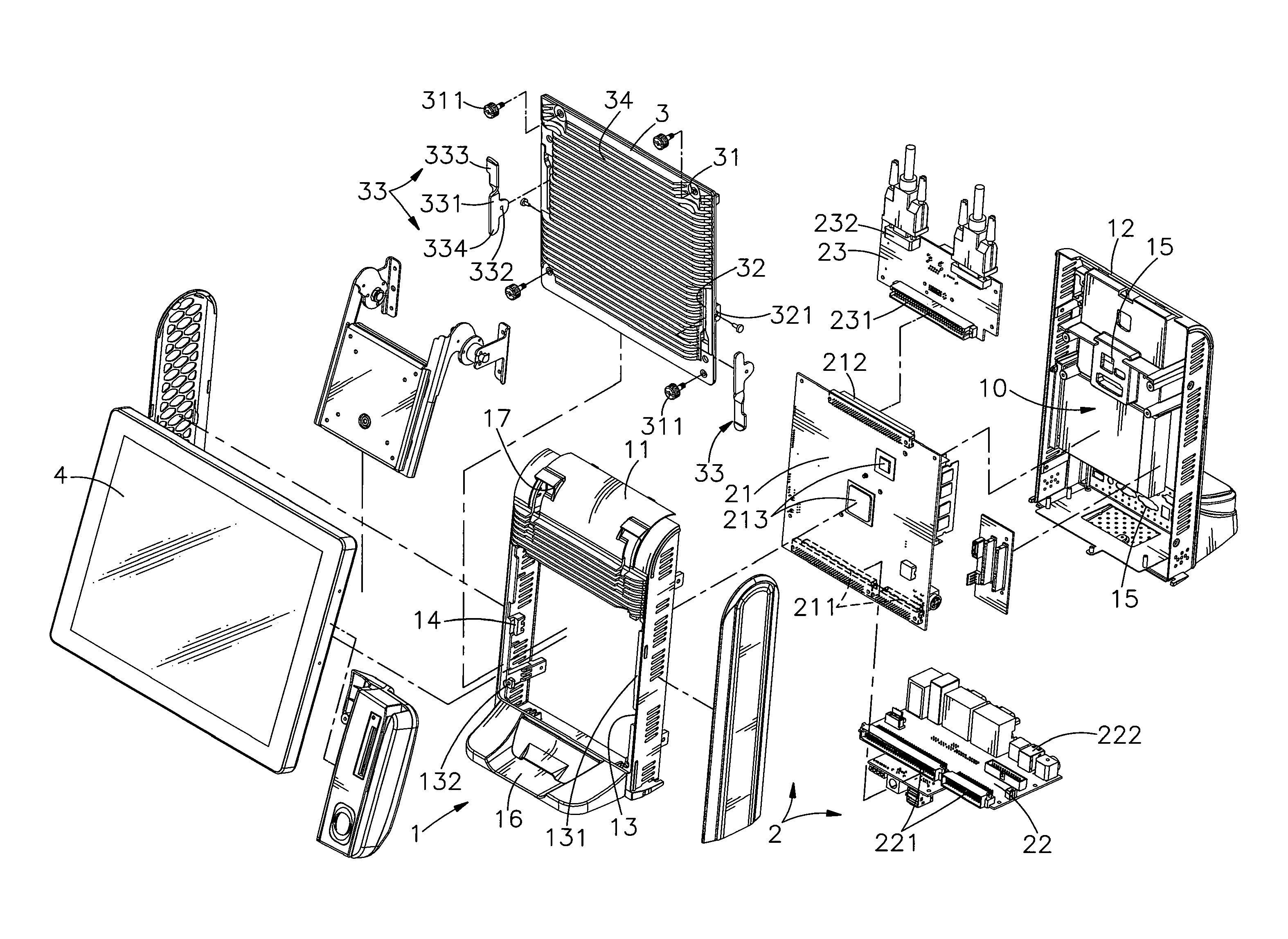
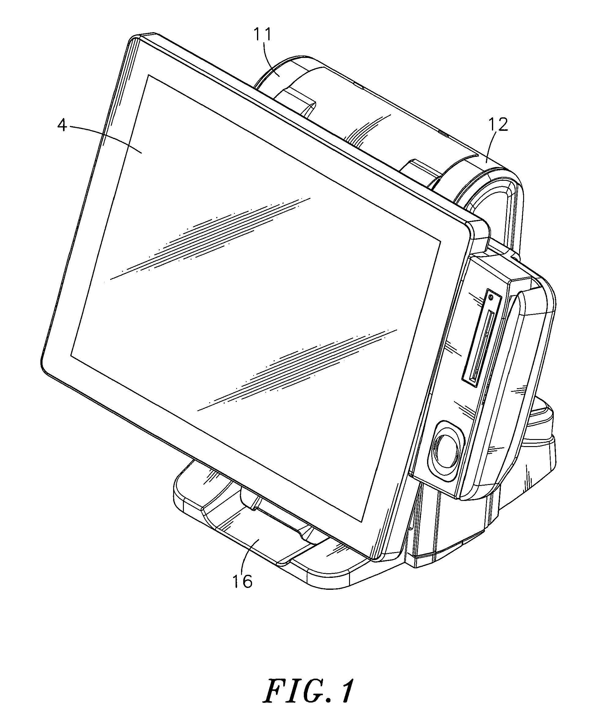
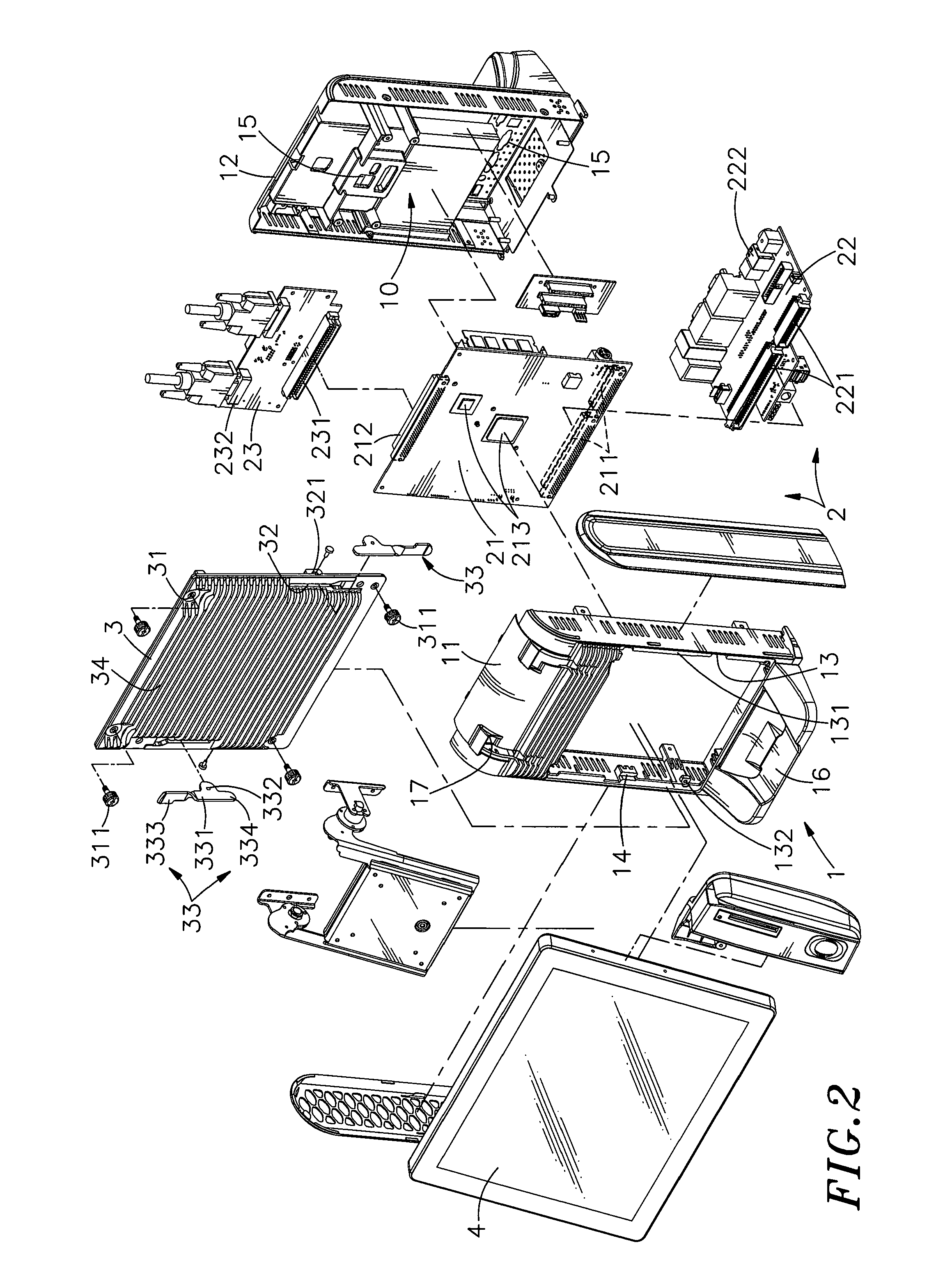
[0021]Referring to FIGS. 1˜4, a mainframe structure in accordance with the present invention is shown comprising a housing 1, a circuit module 2 and a cover 3.

[0022]The housing 1 defines therein an accommodation chamber 10. According to this embodiment, the housing 1 consists of a front cover shell 11 and a back cover shell 12. The accommodation chamber 10 is defined in between the front cover shell 11 and the back cover shell 12. Further, the housing 1 comprises a front opening 13 located on the front wall (front cover shell 11) thereof, a plurality of flanges 131 and mounting holes 132 respectively disposed around the front opening 13 on the same plane, a plurality of stop members 14 suspending on the inside and respectively aimed at the flanges 131 at the same elevation, a plurality of through holes 15 cut through, for example, the back wall (back cover shell 12) thereof, and a forwardly and backwardly expanded base 16 located on the bottom side thereof (formed of a part of the f...


PUM


Abstract

A mainframe structure includes a housing having a front opening, flanges on one same plane around the front opening and stop members suspending on the inside corresponding to the flanges, a circuit module accommodated in the housing, and a cover detachably mounted in the front opening of the housing and stopped against the flanges and the stop member. The cover has two slots symmetrically disposed at two opposite lateral sides, two lugs respectively disposed adjacent to the slots and two handles respectively mounted in the slots and pivoted to the lugs in reversed directions. By means of biasing the two handles to stop against respective stop members, the user can detach the cover from the housing conveniently with the hands without any hand tools.

Description

BACKGROUND OF THE INVENTION[0001]1. Field of the Invention[0002]The present invention relates to computer mainframe design technology and more particularly, to a mainframe structure, which allows quick removal of a cover from an opening on one side of the accommodation chamber of the housing thereof by means of operating multiple handles that are pivoted to the cover, facilitating maintenance.[0003]2. Description of the Related Art[0004]Following fast development of electronic technology, many advanced electronic products, such as computer, cash register, auto teller machine, ticket vending machine and etc., are created and intensively used in fixed places in our daily living. The application of these advanced electronic devices saves much labor and cost. Using electronic devices to perform money counting and number calculation works, avoiding human error. For the advantages of word processing, communication and data inquiry functions and under the environment of high internet popul...

Claims


Application Information

Patent Timeline
Patent Type & Authority Applications(United States)
IPC IPC(8): H05K5/00
CPCG06F1/181G06F1/185G06F1/184
Inventor KU, KANGLIU, HSIEN-TANGLIU, WEN-CHENG
Owner DATAVAN INT
Why Eureka
Try Eureka